MOUNTING 4
8022965-17I6/2020-03-19|SICK
Subject to change without notice
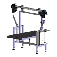
ORIGINAL OPERATING INSTRUCTIONS| VMS4200/5200 (Multicontroller)
4.2 Mounting the incremental encoder
Fig. 59: Attaching the incremental encoder to the conveyor belt (optional)
▸
Install the incremental encoder directly on the conveyor belt.
▸
NOTE! Select an installation site near the circulation rollers or at the end of the belt,
where the belt runs with little vibration.
▸
Tightly screw the incremental encoder to the mounting bracket. Align the incremental
encoder so that it is plane-parallel with the reference plane (bottom side of conveyor
belt).
4.3 Mounting the trigger photoelectric retro-reflective sensor
Fig. 60: Mounting the object detection photoelectric sensor
Legend
1 Clinch stud. Secures the object detection photoelectric sensor to the
mounting bracket.
2 M5 hexagon screws
▸
Mount the object detection photoelectric sensor on the mounting bracket using the
two M5 hexagon screws.
▸
Secure the photoelectric sensor using the clinch stud.
▸
Align the photoelectric sensor correctly on the reflector. The reflector must be
positioned within the beam path of the object detection photoelectric sensor.
Mounting
Mounting