SYSTEM DESCRIPTION 3
8022965-17I6/2020-03-19|SICK
Subject to change without notice
ORIGINAL OPERATING INSTRUCTIONS| VMS4200/5200 (Multicontroller)
3 System description
3.1 Scope of delivery
NOTE!
▸
After delivery, inspect the system for transport damage and report any such damage
immediately.
▸
Check that the delivery includes all components listed on the delivery note.
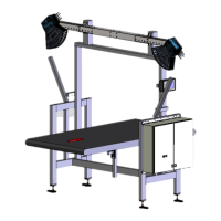
System components
• 2 LMS4421R-16000 2D LiDAR sensors with laser protective cover for the VMS4200
(Multicontroller) or
2 LMS4521R-16000 2D LiDAR sensors with laser protective cover for the VMS5200
(Multicontroller)
• 1 LFT display - VMS5200 (Multicontroller) only
• 1 SIC2000 cabinet with a SIM2000 system controller, power supply unit module, and
Ethernet switch
• 1 incremental encoder with mounting kit (e.g., DFV60, DBS36)
• 1 modular mounting set
• 2 beam blockers
• Connecting cables
Optional
• 1 photoelectric retro-reflective sensor for triggered systems (e.g., RAY26)
• 1 cabinet of the VMS4200/5200 (Multicontroller) with a SIM2000 system controller
and a separate SIM2000 dimensioning controller. This increases the computing power
of the system, thereby allowing a higher throughout as well as enabling complex
identification solutions to be implemented.
• 1 deflector mirror for reducing the mounting height of the 2D LiDAR sensors