ELECTRICAL INSTALLATION 5
8022965-17I6/2020-03-19|SICK
Subject to change without notice
ORIGINAL OPERATING INSTRUCTIONS| VMS4200/5200 (Multicontroller)
5.3.2 VMS4200/5200 (Multicontroller)
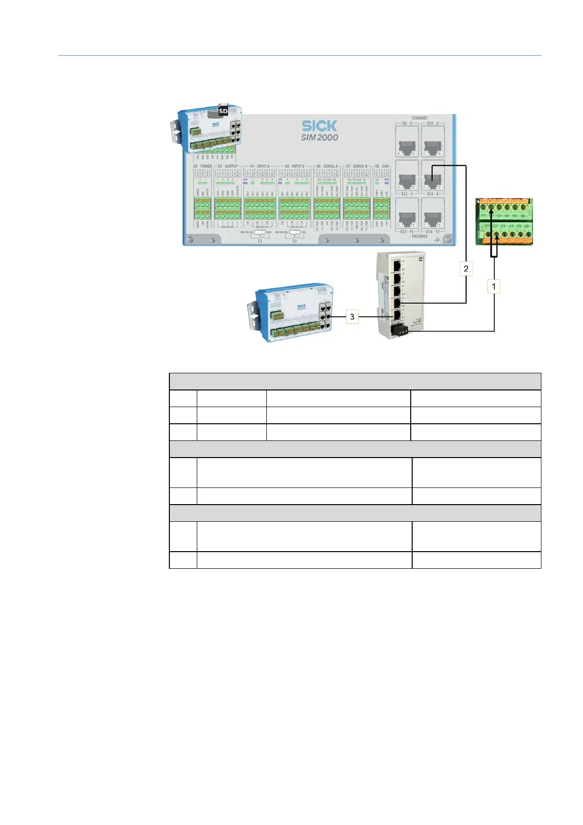
Fig. 67: Connection for the Ethernet switch (set up at the factory)
Voltage supply
No. Wire color Area on fuse block Connection
Red F1_6A 12 +
Dark blue F1_6A 22 -
Ethernet connection to the system controller
No. Connection to the Ethernet switch Port on the SIM2000
(system controller)
2 X4 X12 -4
Ethernet connection to the dimensioning controller
No. Connection to the Ethernet switch Port on the SIM2000
(dimensioning controller)
3 X5 X12 -4
Tab. 12: Connection for the Ethernet switch (set up at the factory)