ARTDriveG Instruction manual Chapter 5 - Wiring Procedure • 37
5.2.2 Rectification and Intermediate (D.C.) Circuit
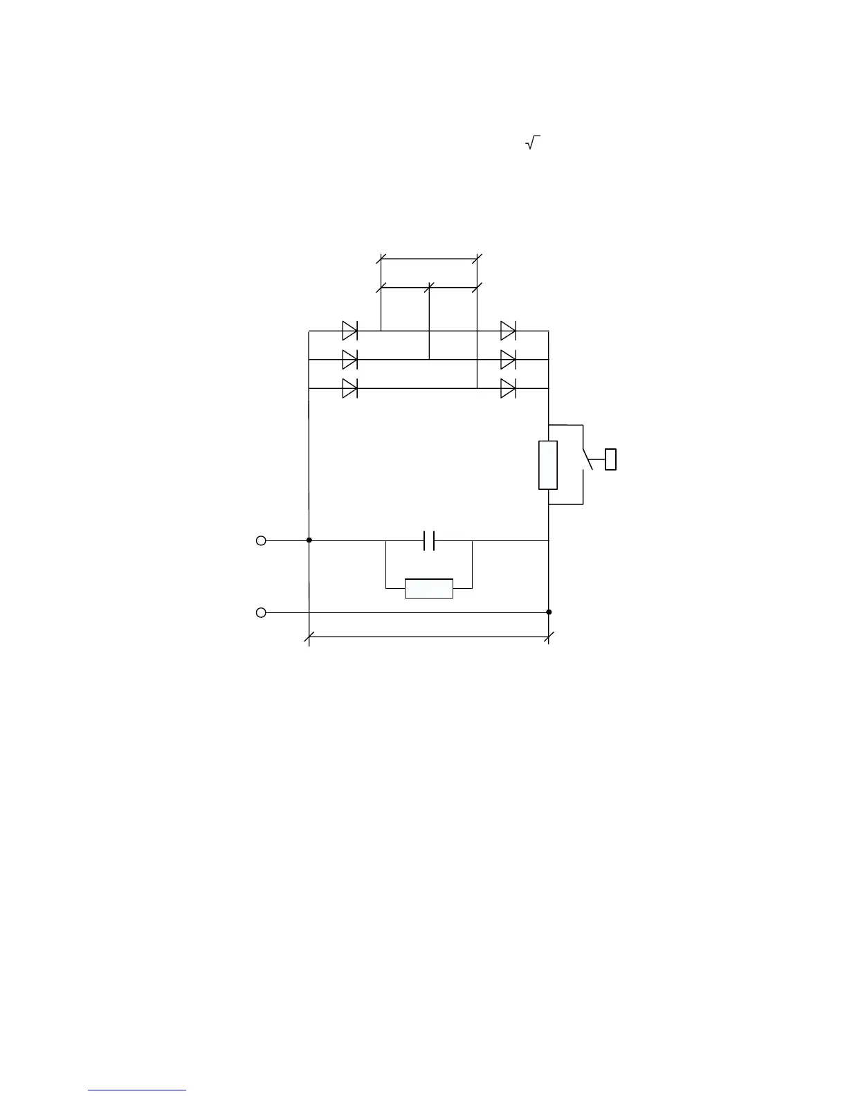
The mains voltage is rectified and buffered by capacitors. A diode bridge with a pre-charging resistor is mounted for all sizes.
In the event of an overvoltage in the intermediate circuit (message “OV” appears in the display) or undervoltage (message
“UV”), the Inverter blocks and no power can be taken from the intermediate circuit.
In normal operation the intermediate (DC) circuit voltage U
DC
is equal to U
LN
* 2. With oversynchronous operation of the
connected motor (deceleration or braking phase), energy is fed back into the intermediate circuit via the Inverter, resulting
in an increase in the intermediate (DC) circuit voltage U
DC
. Once a certain voltage is reached the Inverter is blocked, the
contact between terminals 2 and 3 (alarm relay) will open. To RESET, see paragraph 7.6, Autoreset Configuration section.
D
C
U
DC
U
LN
U
LN
U
LN
Figure 5.2.3.1: Rectification and Intermediate Circuit
The automatic restart of the Inverter can be obtained after a fault indication condition has occurred (for further information
of these functions see paragraph 7.6, Autoreset Configuration section). Switching off can be prevented by extending the
deceleration ramp or by the use of a suitable braking unit (see 5.8).


 To Next Page