ARTDriveG Instruction manual Chapter 5 - Wiring Procedure • 41
5.4 Serial Interface
5.4.1 In General
The RS 485 serial line on the drives of the AGy series allows the data transmission through a loop made of two symmetrical
conductors, which are twisted with a common shield. The maximum transmission speed is 38.4 KBaud.
The transmission is performed via a standard RS 485 differential signal (half-duplex).
With the Multidrop configuration it is possible to connect a maximum of 32 AGy drives
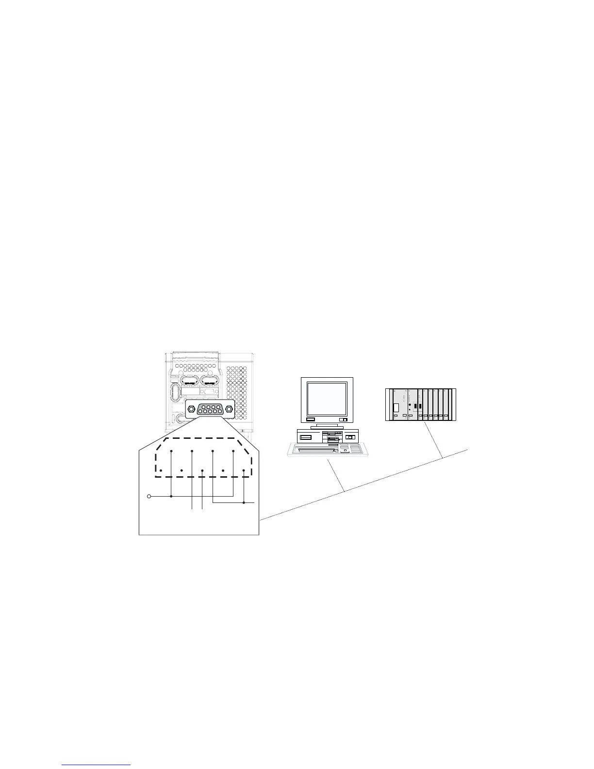
JP7 serial connector
The RS 485 serial line is supplied with a 9-pole SUB-D connector, named JP7, placed on the regulation card of the AGy drive.
The differential signal is transmitted on the Pin 3 (TxA/RxA) and on the Pin 7 (TxB/RxB). In order to avoid the reflection on
the cables, the termination resistance, by selecting J4 yumper.
NOTE!
As for the connection of the serial line, make sure that the power cables and the cables controlling the
contactors and the auxiliary relays are located into different panduits.
Serial protocol
The serial protocol is set via the “I.600 - Serial link cfg” parameter, which allows the selection of the following types:
proprietary protocol FoxLink, RTU Modbus (default) and Jbus.
The serial address is set via the “I.602 - Device address” parameter. Further details about the parameter transmission,
the parameter type and the value range can be found in the tables of Chapter 7.1 (INTERFACE Menu / Serial Configuration).
For the RTU Modbus Protocol see chapter 8.1 of this manual.
JP7
6
7
8
9
5
4
3
2
1
+5V
GND- D
LINK-
LINK+
Figure 5.4.1.1: RS485 Serial Interface