ARTDriveG Instruction manual Chapter 5 - Wiring Procedure • 35
5.2 Power Section
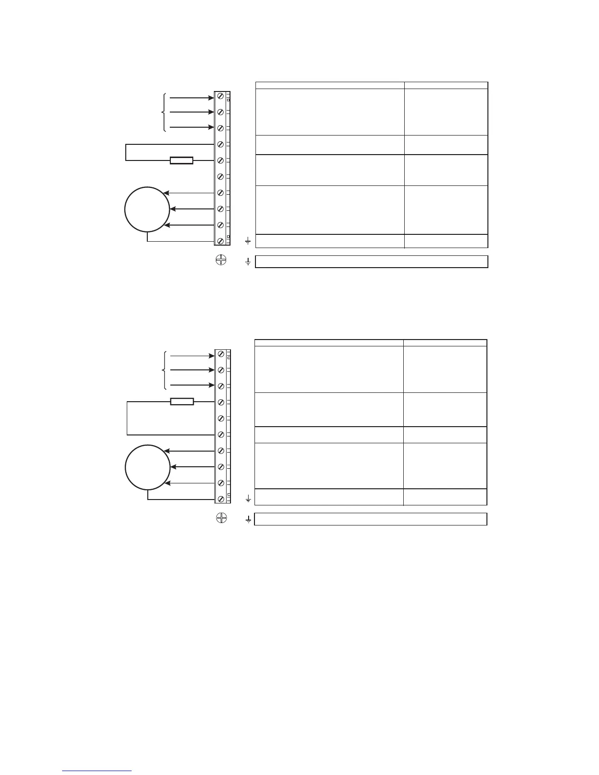
Table 5.2.1.1: Power Section Terminals for Sizes 1007...3150 (230V...480V) and 2002...3020 (575V)
Motor ground connection
Braking unit resistor command (braking resistor
must be connected between BR1 and C)
Intermediate circuit connection
770 VDC (230...480 VAC)
900 VDC (575 VAC)
1.65 x I
2N
AC mains voltage
230V -15% … 480V +10%
or 575 V ±10%
See table 3.3.2.1
Motor connection
3xU
1.36xI
LN
2N
Braking resistor (optional)
Grounding (protective earth) conductor
Function
Max
M
3Ph~
PE1 /
U1/L1
V1/L2
W1/L3
BR1
U2/T1
V2/T2
W2/T3
C
D
PE2/
Table 5.2.1.2: Power Section Terminals for Sizes 4220...71320 (230V...480V) and 4025...5075 (575V)
Braking resistor (optional)
M
PE1 /
U1/L1
V1/L2
W1/L3
BR1
U2/T1
V2/T2
W2/T3
C
D
PE2/
Max
Function
3Ph~
770 Vdc (230...480 Vac)
900 Vdc (575 Vac
1.65 x I
2N
3xU
LN
1.36 x I
2N
Motor ground connection
Intermediate circuit connection
AC mains voltage
Motor connection
Grounding (protective earth) conductor
230V -15% … 480V +10%
or 575 V 10%
See table 3.3.2.1
±
Power terminals lay-out
Sizes 1007...5550 (230V...480V) and
2002... 3020 (575V) The terminals of the devices are made accessible by removing the cover and
the cable entry plate (see section 5.1, “Accessing to the connectors”), on some
drive type it is also possible to extract the removable connector. All the power
terminals are located on the PG33 power card.
Sizes 6750...71320 (230V...480V) and
6100...8200 (575V) The terminals of the devices are made accessible by removing the cover (see
section 5.1, “Accessing to theconnectors”).