152 • Chapter 7 - Parameters Description ARTDriveG Instruction manual
DC Link Limit
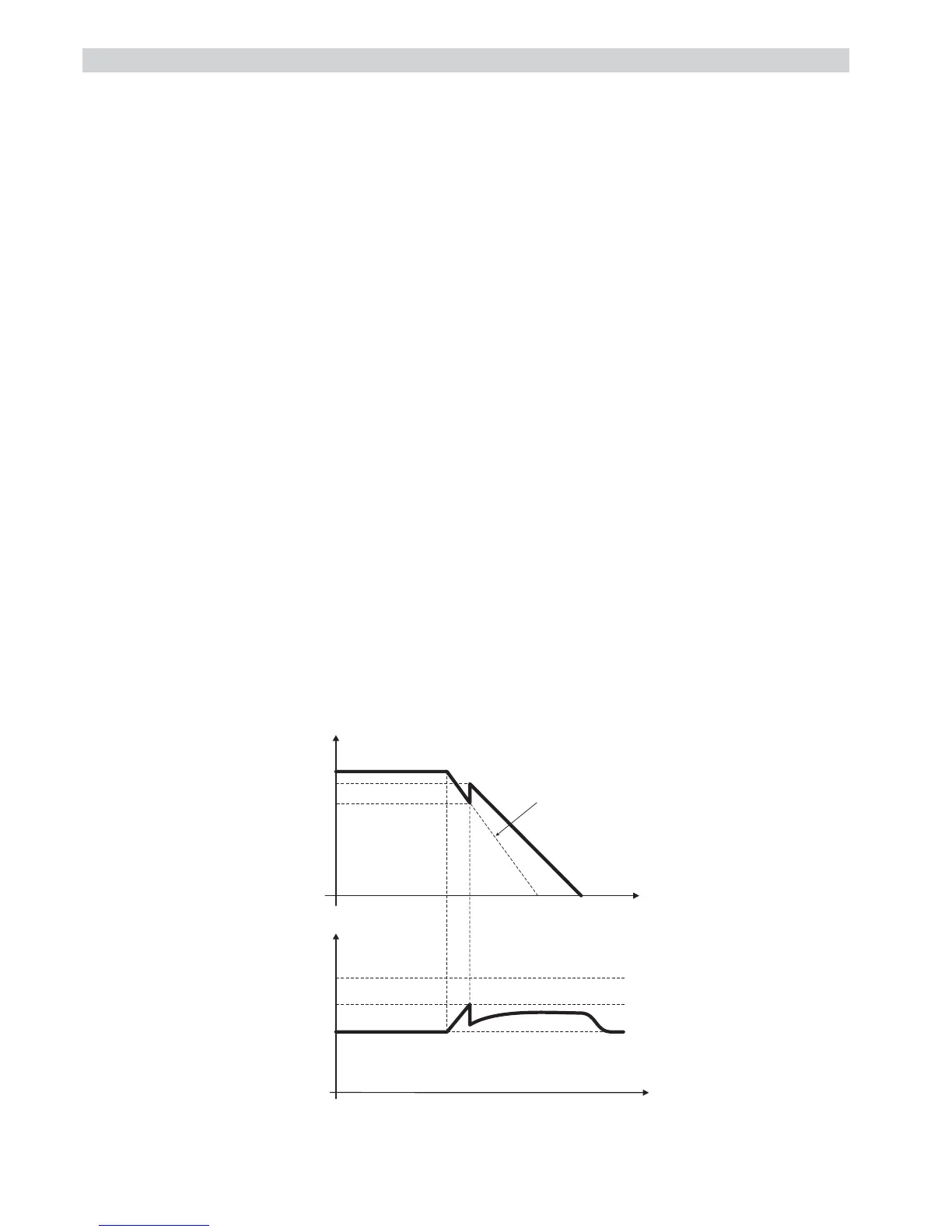
The function controls the voltage level of the DC link bus capacitor.
During fast deceleration, if the load has a big inertia, the DC link value can suddenly increase close to the alarm
threshold. In this case, the output frequency is controlled keeping the voltage level within safe values.
Consequently, the deceleration ramp time is automatically extended, in order to achieve the deceleration of the load,
avoiding an eventual block for "overvoltage" (OV alarm).
As for the current limiter, the DC-Link controller is PI-based, with the addition of a programmable feed forward term.
P.220 En DC link ctrl (Enabling DC link control)
P.220 = 0 Function disabled.
P.220 = 1 Enabling of the DC link control by means of PI regulation of the inverter output frequency.
P.220 = 2 Enabling of the DC link control by ramp freezing.
During fast deceleration, if the DC link level increases close to the alarm threshold, the ramp stage
is momentarily blocked.
As soon as the DC link level returns within the internal safety values, the ramp is restarted.
As a result, the ramp time is lengthened by the execution of this control.
P.221 DC-lnk ctr Pgain (DC link control proportional gain)
Proportional gain of the DC link control regulation.
- a setting too low could cause a slow regulation response.
- a setting too high could cause oscillations of the system.
P.222 DC-lnk ctr Igain (DC link control integral gain)
Integral gain of the DC link control regulation.
- a setting too low can cause a slow regulation response.
- a setting too high can cause oscillations of the DC link.
P.223 DC-link ctr FF (DC link control feed forward)
This is the setting of the feed-forward for the DC bus voltage control function.
As the DC link level increases above a safety threshold, a quick frequency step (percentage of the motor slip) is
automatically added to the reference. The voltage level decreases toward its rated value. The system will be
ready to have effect, when the load generates a DC-link voltage variations to low values near the alarm threshold.
P.223
n
t
Ramp Profile
Set
Safety
V
Dclink
t
0V Thr
RATED
Dclink
Figure 7.6.10: DC Link Voltage Control
A signaling of the "DC link" status is available on the digital output as "DC bus limit".


 To Next Page