ARTDriveG Instruction manual Chapter 5 - Wiring Procedure • 39
5.3 Regulation Section
5.3.1 R-AGy Regulation Card
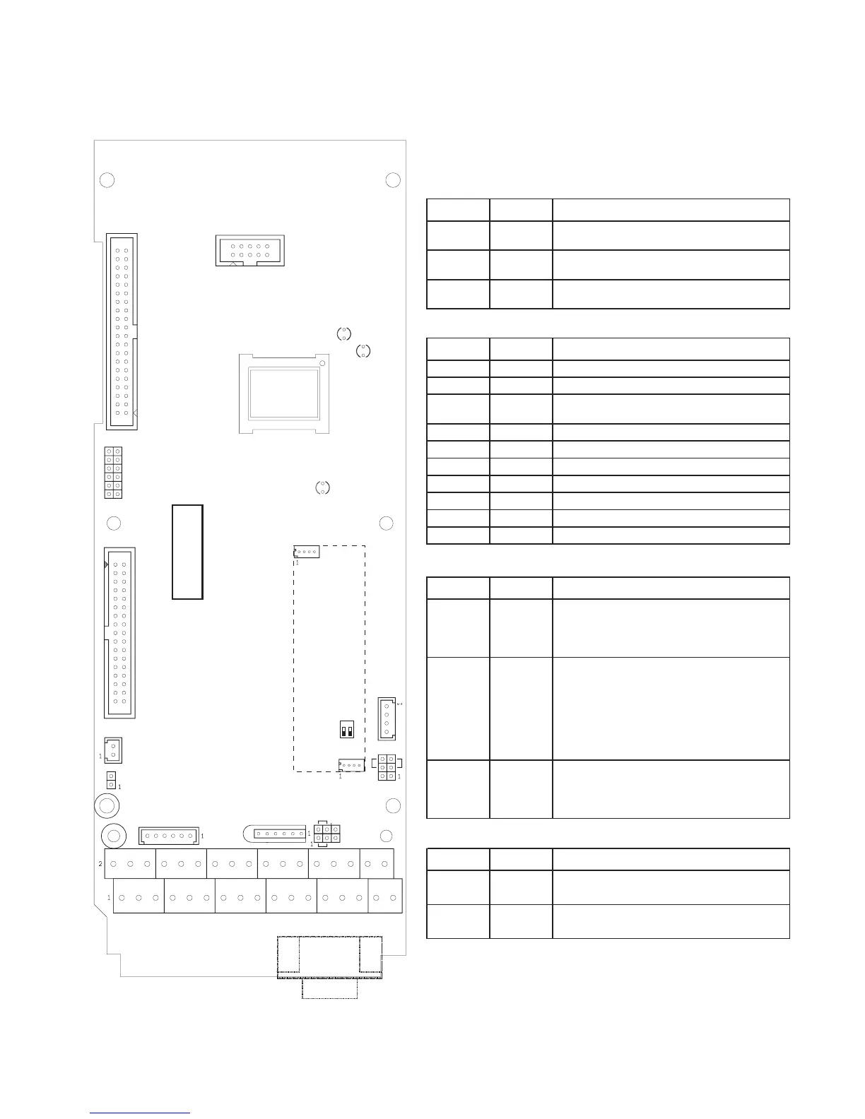
Table 5.3.1.1: LEDs, Jumpers and Connectors on R-GVy-M
LED Color Function
D18 red
LED turns on in drive ALARM condition
D19 green
LED turns on when the voltage + 5V is present
and at correct level
D58 yellow IGBT desaturation or OCH alarm condition
Connector No. of pins Function
J1 2 Reserved (internal use only)
JP2 10 KGB-1 and/or KGB-LCD-A keypad connector
JP6 / JP8 4/4
QUIX-ENC optional board connection (for
encoder feedback)
JP7 9 9-pole SUB-D connector of RS485 serial line
JP10 6 QUIX-PRG key connection
JP12 40 Reserved (power board connection)
JP13A 40 Reserved (expansion boards connection)
JP14 6 QUIX-TST keypad connection
JP15 4 QUIX-REM keypad connection (Serial link)
JP17 14 Reserved (FW download connection)
Jumper Factory Function
Jumper to disconnect 0V (regulation section)
from ground.
ON = 0V connected to ground
OFF = 0V disconnected from ground
Selection of the internal/external supply of the
RS485 serial interface
NONE = Serial interface supplied from the
regulation section
1 = Serial interface supplied from external
source (see chap. 5.4) and
galvanic insulation from the regulation card
Terminating resistor for the serial interface
RS485
NONE = No termination resistor
1 = Termination resistor IN
Switch Factory Switch function of QUIX-ENC optional board
S1-1 OFF
OFF = HTL output logic encoder level (+24V)
ON = TTL output logic encoder level (+5V)
S1-2 OFF
OFF = HTL output logic encoder level (+24V)
ON = TTL output logic encoder level (+5V)
ai4050g
J4
J2
J3
ON
1
1
Figure 5.3.1.1: R-AGy Regulation Card
D19
D18
JP2
JP8
JP13A
D58
JP17
JP12
12
3
47
10 13 1658
11 14 17
69
12
15
20 23 26 29 3219
22 25
28 31 34
18
21 24 27
30 33
1
1
1
R-AGy
J1
J2
JP14
JP10
J3
J4
JP15
JP6
PE
JP7
S1
ON
OFF
QUIX-ENC
(OPTIONAL)
1
2


 To Next Page