ARTDriveG Instruction manual Chapter 5 - Wiring Procedure • 59
Caution
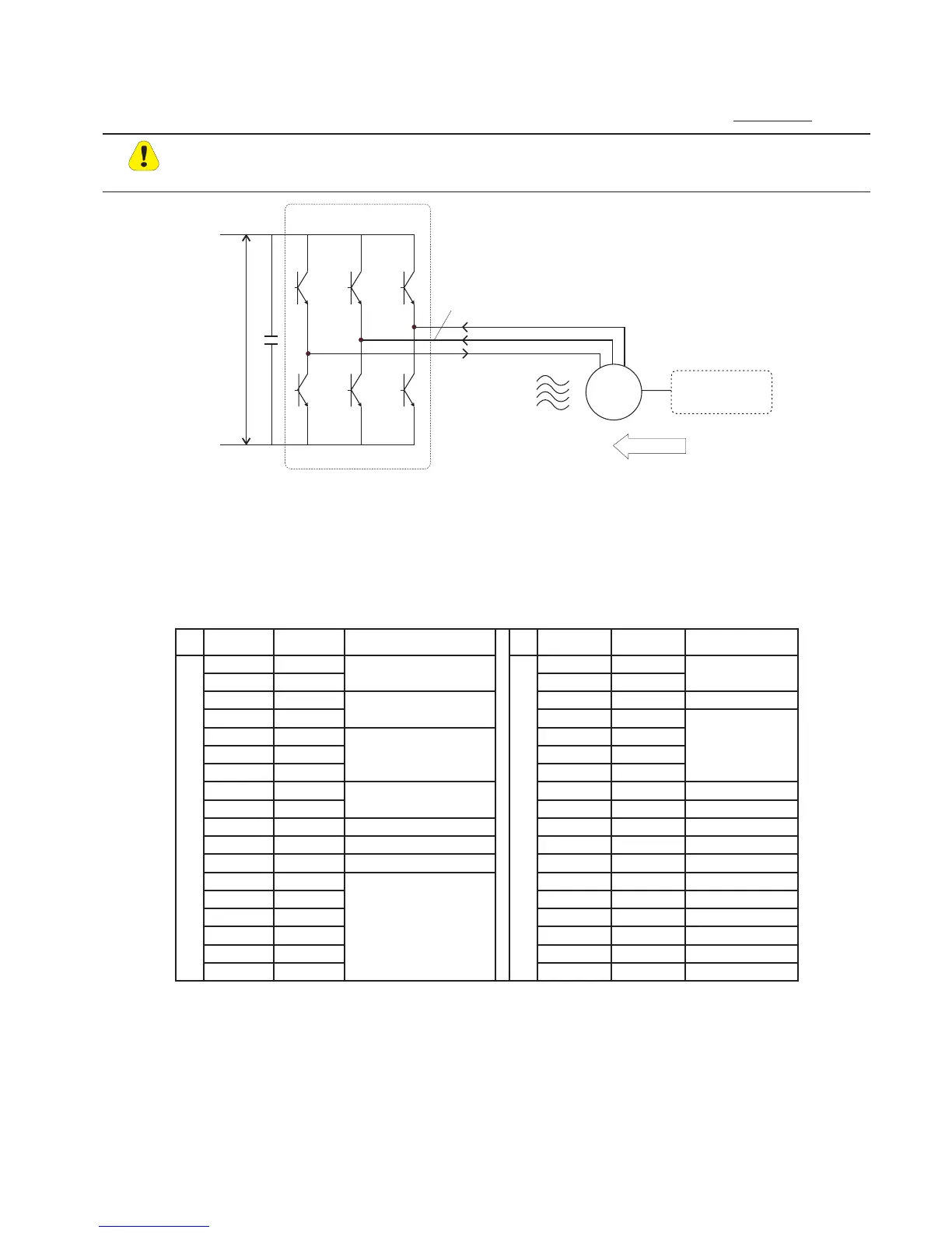
5.8.2 D.C. Braking
The Inverter offers the facility of D.C. braking as a standard. To this end, the Inverter injects D.C. current into two motor
phases, thereby generating braking torque. The kinetic energy of the machine is dissipated as heat in the motor.
This option enables the drive to be braked to a standstill. It does not permit deceleration to a lower
speed. It may be necessary to measure the braking current in the “U” phase.
M
3~
Energy Machine
Energy
U
DC
_
+
Inverter
U
V
W
/2
Figure 5.8.7: D.C. Braking, Schematic
5.9 Discharge Time of the DC-Link
Table 5.9.1: DC Link Discharge Times
Type
I
2N
Time (seconds) Type
I
2N
Time (seconds)
1007 2.1
2002
3.8
1015 3.5
2003
4.5
1022 4.9
2005
7.0
200
1030 6.5
3007
10.8
2040 8.3
3010
13.8
2055 11
3015
18.7
2075 15.4
3020
24.2
3110 21.6
4025
30 230
3150 28.7
4030
36 230
4220
40 60
4040
46 230
4300
54 60
4050
58 300
4370
68 90
5060
69 300
5450
81
5075
86 300
5550
99
6100
109 300
6750
124
7125
137 300
7900
160
7150
158 300
71100
183
8200
218 300
71320
217
agy0708
100
250
AGy…-4 (230V…480V)
AGy…-5 (575V)
120
90
150
205
220
This is the minimum time that must be elapsed since an AGy Drive is disconnected from the AC Input before an operator
may service parts inside the Drive to avoid electric shock hazard.
CONDITION:
These values consider a turn off for a Drive supplied at 480Vac +10%, without any option, ( the charge
for the switching supply is the regulation card, the keypad and the 24Vdc fans “if mounted”).
The Drive is disabled. This represents the worst case condition.


 To Next Page