58 • Chapter 5 - Wiring Procedure ARTDriveG Instruction manual
Where: V
BR
= braking unit threshold (see table 5.8.1.1)
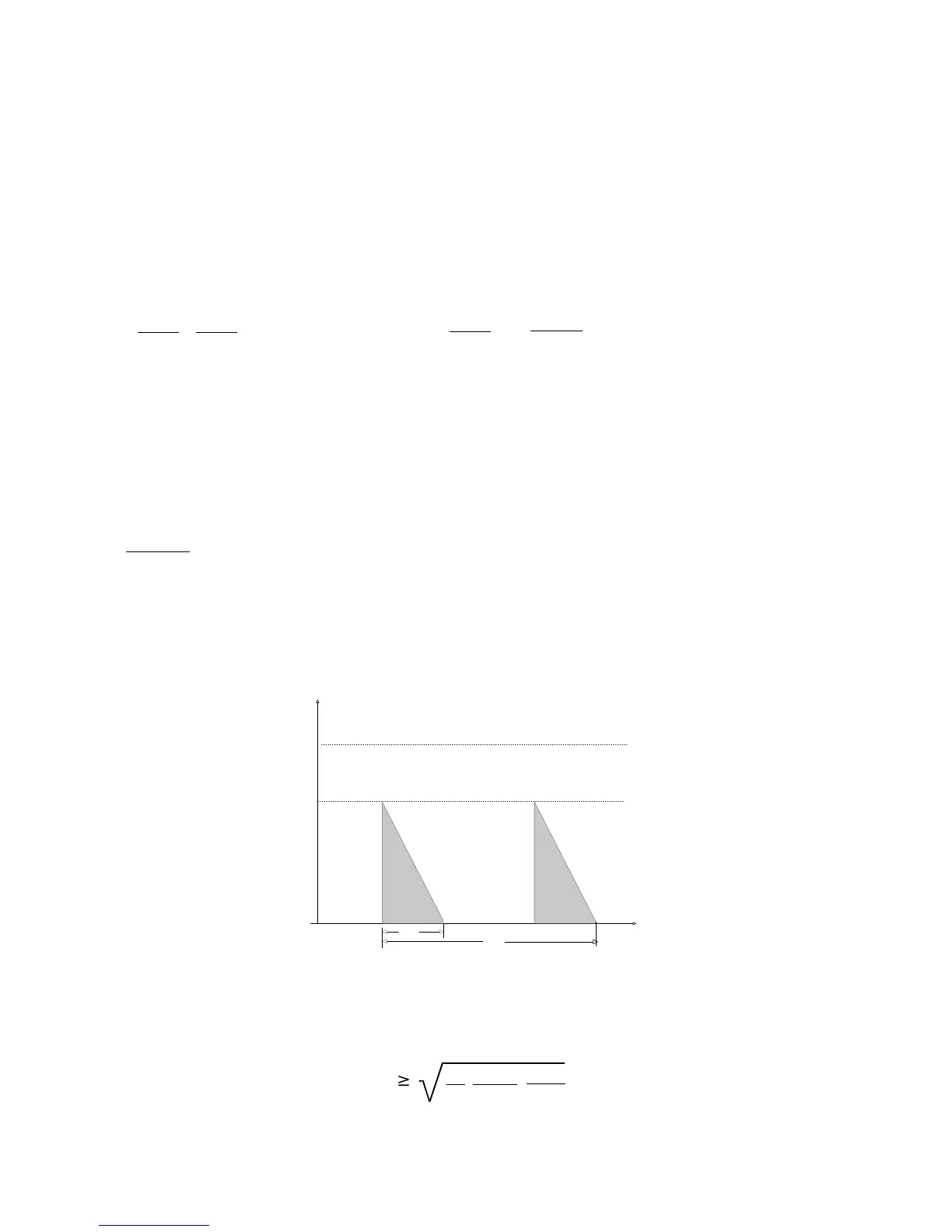
With reference to the figure 5.8.5, where the power profile is the typical triangular one, the following example can be taken
into consideration (see also table 5.8.1.3).
Resistor model: MRI/T600 100R
Nominal power P
NBR
= 600 [W]
Maximum energy E
BR
= 4 x 600[W] x 10[s] = 24000[J]
Inverter mains supply = 460V
From table 5.8.1.1: V
BR
=780V
T
BRL
=
2
E
BR
P
PBR
=
24000
6084
=
7.8[s]2
P
PBR
=
V
BR
R
BR
2
=
780
100
2
=6084 [W]
It is necessary to consider the following relation:
A) If T
BR
≤≤
≤≤
≤ E
BR
/ P
NBR
verify:
1) P
MB
≤≤
≤≤
≤ 2 . E
BR
/ T
BR
Where: P
MB
is the average power of the cycle (see.fig. 5.8.5)
2)
PxT
2T
MB BR
C
P
NBR
The average power of the cycle must not be higher than the nominal power of the resistor.
B) If T
BR
>>
>>
> E
BR
/ P
NBR
that is to say, in case of very long braking time, it must be dimensioned P
MB
≤ ≤
≤ ≤
≤ P
NBR
Figure 5.8.5: Generic braking cycle with triangular profile
T
C
n,P
P
PBR
T
BR
t
P
MB
If one of the above mentioned rules is not respected, it is necessary to increase the nominal power of the resistor, respecting
the limit of the internal braking unit (reported in table 5.8.1.2).
The table 5.8.1.2 can be used to choose an external resistor, different from the standard series. Generally the following
condition must be satisfed
I
RMS
1P T
PBR BR
RT
BR C
2
In case of using more external BUs, each BU with a resistor (all the same) refers to the parameters calculation of a single unit.


 To Next Page