40 • Chapter 5 - Wiring Procedure ARTDriveG Instruction manual
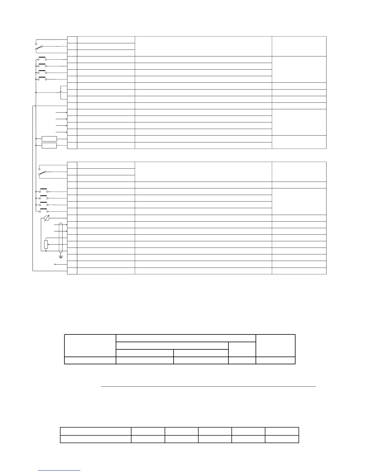
5.3.2 Terminal Assignments on Regulation Section
Strip 1
1
2
3
4
5
6
7
8
9
10
11
12
13
14
15
16
17
Strip 2
18
19
20
21
22
23
24
25
26
27
28
29
30
31
32
33
34
Designation
DigitalOutput4-NO
Digital Output 4 - COM
DigitalOutput4-NC
Digital Input 8
Digital Input 7
Digital Input 6
Digital Input 5
COM-IN Digital Inputs
+ 24V OUT
0 V 24 - GND Dig. Inputs
0 V 24 - GND Dig. Inputs
A+ Encoder channel
A - Encoder channel
B+ Encoder channel
B - Encoder channel
Digital Output 1
Digital Output 2
Function
Programmable digital relay output - Default:
Programmable digital input - Default:
Programmable digital input - Default:
Programmable digital input - Default:
Programmable digital input - Default:
Supply reference for Digital inputs
+ 24 V potential voltage reference
V 24 reference for Digital inputs
0 V 24 reference for Digital inputs
A+ encoder channel input (QUIX-ENC expansion board required)
A - encoder channel input (QUIX-ENC expansion board required)
B+ encoder channel input (QUIX-ENC expansion board required)
B - encoder channel input (QUIX-ENC expansion board required)
Programmable digital output - Default:
Programmable digital output - Default:
[1] Alarm state
[2] Reverse
[1] Run
[3] Ext fault NO
[5] Alarm reset
[0] Drive ready
[6] Steady state
Max
230Vac 0.2A
125Vac 0.3A (UL rating)
110Vdc 0.3A (UL rating)
30Vdc 1A (UL rating)
Designation
DigitalOutput3-NO
Digital Output 3 - COM
DigitalOutput3-NC
GROUND REF
Digital Input 1
Digital Input 2
Digital Input 3
Digital Input 4
Analog Output 1
Analog Input 2
Analog Input 3
+ 10V OUT
Analog Input 1
0V10-GND
- 10V OUT
Analog Output 2
COM Digital outputs
Function
Programmable digital relay output - Default:
Ground shield cable reference
Programmable digital input - Default:
Programmable digital input - Default:
Programmable digital input - Default:
Programmable digital input - Default:
Programmable analog output - Default:
Programmable VOLTAGE analog input - Default: ±
Programmable CURRENT analog input - Default:
+ 10 V potential voltage reference
Programmable VOLTAGE analog input - Default:
0 V 10 reference for analog inputs/outputs
- 10 V potential voltage reference
Programmable analog output - Default:
Common reference for Digital outputs
[3] Motor running
[7] Freq sel 1
[8] Freq sel 2
[28] Stop (3wires)
[6] Jog
[0] Freq out abs
[0] 10V
[1] 0…20mA
[0] 0...10V
[0] Output curr
Max
230Vac 0,2A
125Vac 0.3A (UL rating)
110Vdc 0.3A (UL rating)
30Vdc 1A (UL rating)
-
6mA @ +24V
-
+24V / 300mA
-
-
HTL 24V / 17mA
TTL 5V / 9mA
+50V / 50mA
6mA @ +24V
±10V / 5mA
±10V / 0.5mA
20mA
+10V / 50mA
±10V / 0.5mA
-
-10V/50mA
±10V / 5mA
-
LOAD
LOAD
Figure 5.3.2.1: Plug-in Terminal Strip Assignments
Maximum Cable Sizes for control terminals
Table 5.3.2.1: Maximum Permissible Cable Cross-section on the Plug-in Terminals of the Regulator Section
Maximum Permissible Cable Cross-Section Tightening
torque
flexible multi-core Nm (lbt. inch)
1 ... 34 0.5 … 1.5 (0.02…0.06) 0.5 ...1.5 (0.02…0.06) 28 …16 0.4 (35.4)
TGy0160
AWG
Terminals
mm
2
(inch)
The use of a 75 x 2.5 x 0.4 mm (3 x 0.1 x 0.02 inch) flat screwdriver is recommended. Remove 6.5 mm (0.26 inch) of the
insulation at the cable ends. Only one unprepared wire (without ferrule) should be connected to each terminal point.
Maximum Cable Length
Table 5.3.2.2: Maximum Control Cable Lengths
Cable section [mm
2
]
0.22 0.5 0.75 1 1.5
Max Length m [feet] 27 [88] 62 [203] 93 [305] 125 [410] 150 [492]
avy3130