ARTDriveG Instruction manual Chapter 5 - Wiring Procedure • 49
5.7.1 AC Input Chokes
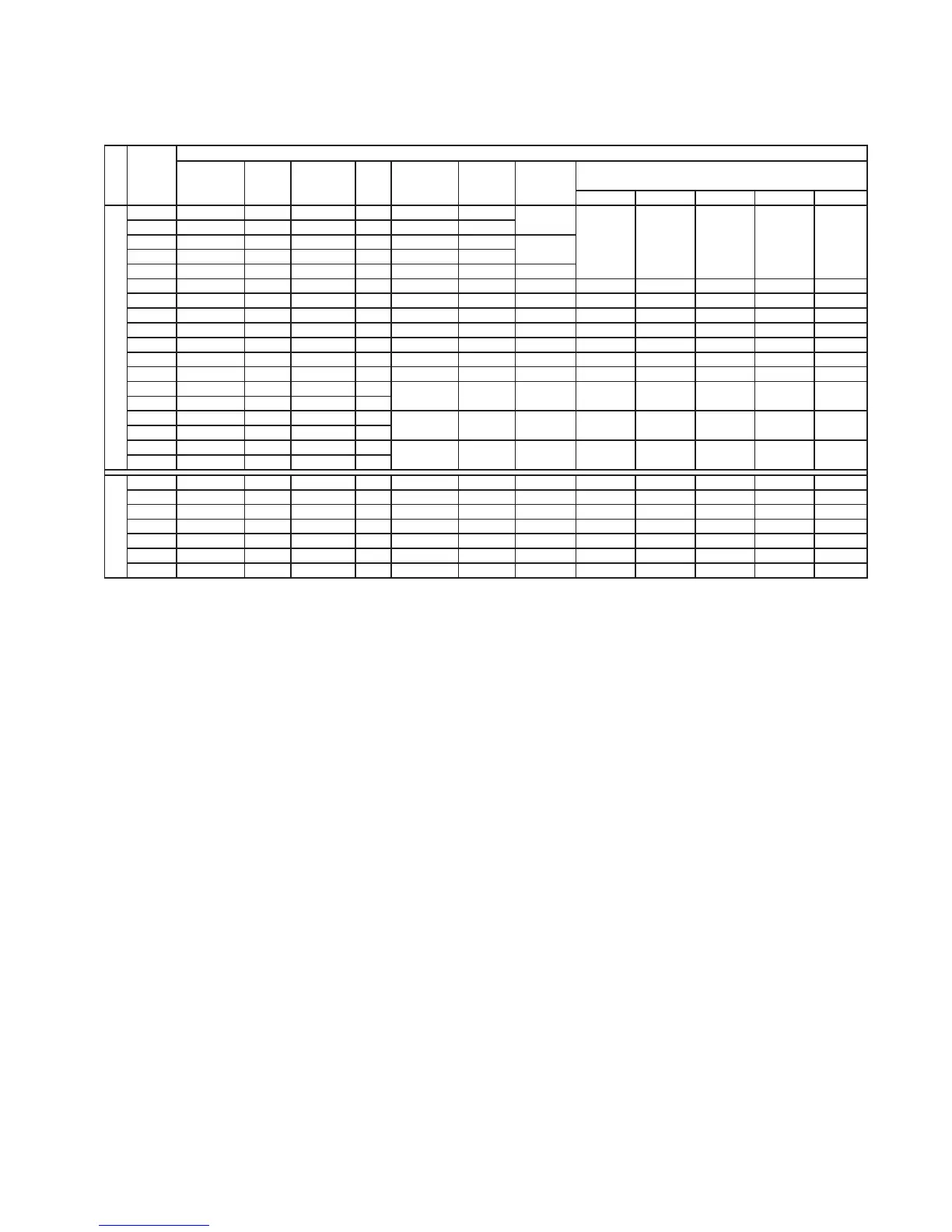
Table 5.7.1.1: 3-Phase AC Input Chokes
Mains
inductance
Rated
current
Saturation
current
Freq.
[mH] [A] [A] [Hz] a b c D1 E1
1007 6.1 2.5 5 50/60 LR3y-1007 S7AAD
1015 3.69 3.7 7.4 50/60 LR3y-1015
S7AAE
1022 2.71 5.5 11 50/60 LR3y-1022
S7AAF
1030 2.3 6.7 14 50/60 LR3y-1030
S7AB3
2040 1.63 8.7 18 50/60 LR3y-2040
S7AAG 2 (4.4)
2055 1.29 11.8 24.5 50/60 LR3y-2055 S7AB5
2.2 (4.4) 120 (4.7) 125 (4.9) 75 (2.6) 100 (3.9) 55 (2.2)
2075 0.89 17.4 36.5 50/60 LR3y-2075 S7AB6
4.9 (10.8) 150 (5.9) 155 (6.1) 79 (3.1) 90 (3.5) 54 (2.1)
3110 0.68 22.4 46.5 50/60 LR3y-3110 S7AB7
5 (11) 150 (5.9) 155 (6.1) 79 (3.1) 90 (3.5) 54 (2.1)
3150 0.51 30 61 50/60 LR3y-3150 S7AB8
6.2 (13.7) 150 (5.9) 168 (6.6) 100 (3.9) 90 (3.5) 69 (2.7)
4220 0.35 41 83 50/60 LR3-022
S7FF4 7.8 (17.2) 180 (7.1) 182 (7.2) 130 (5.1) 150 (5.9) 70 (2.8)
4300 0.24 58 120 50/60 LR3-030
S7FF3 9.5 (20.9) 180 (7.1) 160 (6.3) 170 (6.7) 150 (5.9) 80 (3.1)
4370 0.18 71 145 50/60 LR3-037
S7FF2 9.5 (20.9) 180 (7.1) 160 (6.3) 180 (7.1) 150 (5.9) 80 (3.1)
5450 0.13 102 212 50/60
5550 0.13 102 212 50/60
6750 0.148 173 350 50/60
7900 0.148 173 350 50/60
71100 0.085 297 600 50/60
71320 0.085 297 600 50/60
2002 4.5 4.2 8.4 50/60 LR3y-5-002
S7AD0 2 (4.4) 120 (4.7) 125 (4.9) 75 (2.6) 100 (3.9) 42 (1.6)
2003 3.8 5.2 10.4 50/60 LR3y-5-003
S7AD2 2 (4.4) 120 (4.7) 125 (4.9) 75 (2.6) 100 (3.9) 42 (1.6)
2005 2.3 8.1 16.2 50/60 LR3y-5-005
S7AD3 2.7 (6) 120 (4.7) 125 (4.9) 85 (3.3) 100 (3.9) 52 (2)
3007 1.5 12.9 25.8 50/60 LR3y-5-007
S7AC7 5 (11) 150 (5.9) 152 (6) 80 (3.1) 90 (3.5) 55 (2.2)
3010 1.2 16.5 33.0 50/60 LR3y-5-010
S7AC8 5 (11) 150 (5.9) 152 (6) 80 (3.1) 90 (3.5) 55 (2.2)
3015 0.9 21.8 43.6 50/60 LR3y-5-015
S7AC9 5.5 (12.1) 150 (5.9) 164 (6.4) 96 (3.8) 90 (3.5) 60 (2.4)
3020 0.7 28.5 57 50/60 LR3y-5-020
S7AD1 6.2 (13.7) 150 (5.9) 164 (6.4) 106 (4.2) 90 (3.5) 70 (2.8)
agy0703
120 (4.7)
AGy…-5 (575V) AGy…-4 (230V…480V)
Drive
type
LR3-055
LR3-090
LR3-160
Three-phases main chokes
80 (3.1)
S7D40
85 (3.3)
Model
Weight
kg (lbs)
12.5 (27.6)
55 (121.3)
SIEI code
S7FF1
S7D19
215 (8.5) 180 (7.1)
44 (97.0)
Dimensions : mm (inch)
120 (4.72) 125 (4.92) 65 (2.56) 100 (3.94) 45 (1.77)
1.8 (3.9)
1.9 (4.2)
240 (9.4) 150 (5.9)
300 (11.8) 265 (10.4) 210 (8.3) 250 (9.8)
300 (11.8) 270 (10.6) 260 (10.2) 250 (9.8)
For sizes up to 20Hp, an input choke is strongly reccomended in order to:
- prolong the life time of the DC link capacitors and the reliability of the input rectifier.
- reduce the AC line harmonic distortion
- reduce problems due to low impedence AC line (≤ 1%).
NOTE!
The current rating of these chokes (reactors) is based on nominal current of standard motors, listed in
table 3.3.4.1 in section 3.3.4, “AC Output”.
NOTE!
The 4025 … 8200 sizes of AGy-5 series (575Vac), integrate as standard the input choke on intermediate
circuit (DC-Link). With this configuration the three phase input choke it is NOT required.
5.7.2 Output Chokes
The AGy Drive can be used with general purpose standard motors or with motors specially designed for Drive use. The latter
usually have a higher isolation rating to better withstand PWM voltage.
Motors designed for use with Adjustable Frequency Drives do not require any specific filtering of the voltage waveform from
the Drive. For general purpose motors and using drives up to 2005 size, especially with long cable runs (typically over 100
m [328 feet]) an output choke is recommended to mantain the voltage waveform within the specified limits. Suggested
choke ratings and part numbers are listed in table 5.7.2.1.
The rated current of the filters should be approx. 20% above the rated current of the frequency Drive in order to take into
account additional losses due to PWM waveform.


 To Next Page