Typical circuit diagrams
10.1 Connection examples for main and control circuits
3RW44 soft starters
220 Manual, 03/2017, NEB535219502000/RS-AB/008
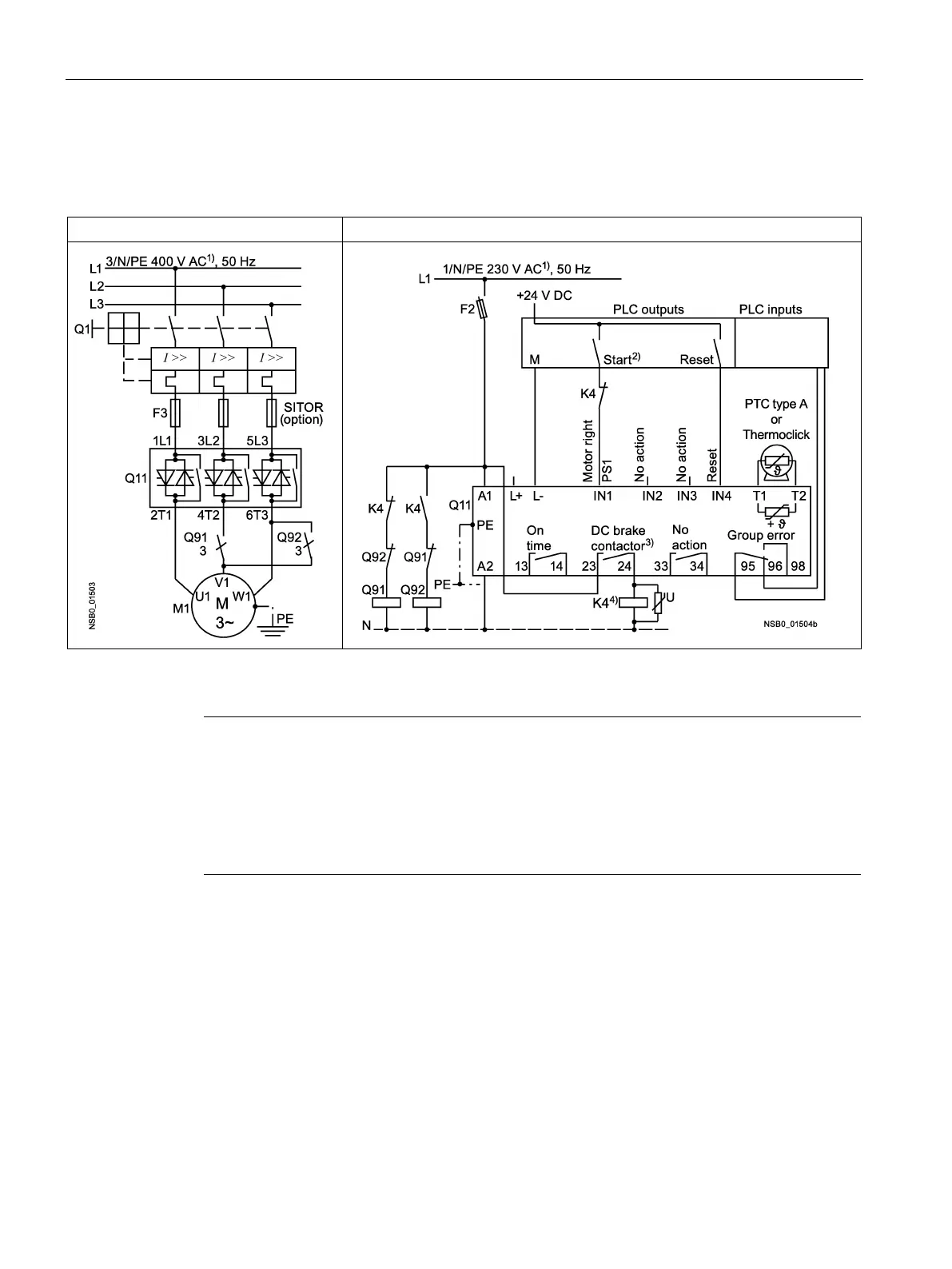
3RW44 in a standard circuit and DC braking stopping function for device types
3RW44 26 to 3RW44 66
1)
For permissible main and control voltage values, refer to chapter Technical data of the
power unit (Page 259).
Note
2)
Risk of restart
The start command (e.g. issued by the PLC) must be reset prior to issuing a reset command,
because the motor attempts to restart again automatically if a start command is still active
following this reset command. This particularly applies if the motor protection has
tripped.
For safety reasons, you are advised to integrate the group fault output (terminals 95 and 96)
in the controller.
3)
If the "combined braking" stopping function is selected, a braking contactor is not required.
A braking contactor must be additionally used if the "DC braking" function is selected. For
types, refer to the "Feeder component layout (standard circuit)" table in chapter Feeder
component layout (standard circuit) (Page 270).
The "DC braking" function is recommended for applications with larger centrifugal masses
(J
load
> J
motor
).
Output 2 must be set to "DC braking contactor".
4)
Auxiliary relay K4, e.g.:
LZS:RT4A4T30 (230 V AC rated control supply voltage),
LZS:RT4A4S15 (115 V AC rated control supply voltage).
 Loading...