Home
Siemens
Control Unit
3RW44
Page 44 (Conductor Cross-Sections)
Siemens 3RW44 - Conductor Cross-Sections
292 pages
Manual
Save Page as PDF
To Next Page
To Next Page
To Previous Page
To Previous Page
Loading...
Installation, conne
ction and feeder
configuration
4.6
Electrical connecti
on
3RW44 soft starters
44
Manual, 03/2017, NEB535219502
000/RS-AB/008
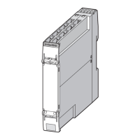
4.6.3
Conductor cros
s
-sections
A1, A2, PE, L+, L
-
, IN1, IN2, IN3, IN4, T1,
T2, 13, 14, 2
3, 24, 33, 34,
95, 96, 98
3RW44..
-
1....
3RW44..
-
6....
3RW44..
-
2....
3RW44..
-
3....
∅
5…6
mm/PZ2
0.8…1.2
Nm
7 to 10.3 lb.in
-
1 x 0.5…4.0
mm
2
2 x
0.5…2.5
mm
2
2 x 0.25…1.5
mm
2
2 x 0.5…1.5
mm
2
1 x 0.5…2.5
mm
2
2 x 0.25…1.5
mm
2
-
2 x 0.25…1.5
mm
2
AWG
2 x 20...14
2 x 24...16
43
45
Table of Contents
Main Page
Default Chapter
4
Table of Contents
4
1 Important Notes
9
Security Information
11
2 Introduction
12
Basic Physical Principles of the Three-Phase Asynchronous Motor and Operating Principle of the Soft Starter
12
Three-Phase Asynchronous Motor
12
Principle of Operation of the 3RW44 Electronic Soft Starter
14
Application and Use
17
Marginal Conditions for Storage and Operation
19
3 Configuration Instructions
20
Configuration
20
RS 232 Serial PC Interface and Soft Starter es Parameterizing and Operating Software
20
Simulation Tool for Soft Starters (STS)
20
Startup Class
21
Application Examples for Normal Starting (CLASS 10)
22
Application Examples for Heavy Starting (CLASS 20)
23
Application Examples for very Heavy Starting (CLASS 30)
24
ON Time and Switching Frequency
25
Installation Altitude and Ambient Temperature
26
Factory Settings
27
Article Number System for SIRIUS 3RW44 Soft Starters
28
4 Installation, Connection and Feeder Configuration
29
Installing the Soft Starter
29
Unpacking
29
Mounting Position
29
Installation Requirements
30
Mounting Dimensions and Clearances
31
Design of the Feeder
32
General Information
32
Soft Starters in Standard Circuits
33
Soft Starters in Inside-Delta Circuits
35
Soft Starter with Contactor Disconnector (Main Contactor)
38
Protection of the Soft Starter against Short-Circuits (Type of Assignment 2)
40
Capacitors for Improving the Power Factor
41
Generator Operation with Three-Phase Asynchronous Motor
42
Electrical Connection
42
Control and Auxiliary Circuit Connection
42
Main Circuit Connection
42
Conductor Cross-Sections
44
5 Display, Controls and Device Interfaces
46
Display and Controls
46
Device Interfaces
47
Local Device Interface
47
PROFIBUS/PROFINET Interface (Optional)
47
External Display and Control Module (Optional)
47
6 Commissioning
48
Menu Structure, Navigation, Changing Parameters
48
Menu Structure and Navigation
48
Changing Parameters: for Example Motor Data
49
Switching on for the First Time
50
Recommended Procedure for Commissioning 3RW44
50
Quick Start Menu, When Switching on for the First Time
51
Problems that Can Occur
53
Quick Start Menu
56
User-Specific Commissioning
58
Settings Main Menu Item
59
Making Settings in the Selected Parameter Set
60
Selecting the Parameter Set
60
Entering the Motor Data
61
Specifying the Startup Mode
63
Specifying the Coasting Method
75
Setting Slow Speed Parameters
86
Specifying Current Limit Values
88
Parameterizing the Inputs
89
Parameterizing the Outputs
92
Selecting Motor Protection Settings
94
Selecting Display Settings
97
Specifying the Behavior of the Protective Functions
98
Specifying the Names on the Device Display
100
Activating the Fieldbus Interface (PROFIBUS DP/PROFINET IO)
101
Saving Options
102
Other Device Functions
107
Measured Values Display
107
Status Display
109
Motor Control (Assigning Control Priority)
110
Statistics
112
Safety (Specifying the User Level, Parameterization Protection)
118
7 Device Functions
119
Various Parameter Sets
119
Startup Modes
119
Voltage Ramp
119
Torque Control
121
Breakaway Pulse in Combination with the Voltage Ramp or Torque Control Startup Mode
124
Current Limitation in Combination with the Voltage Ramp or Torque Control Startup Mode
125
Direct Startup Mode
127
Motor Heating Startup Mode
127
Coasting Methods
128
Coasting down
129
Torque Control and Pump Stop
129
DC Braking/Combined Braking
131
Slow Speed Function
134
Current Limits for Load Monitoring
135
Motor Protection Functions
136
Intrinsic Device Protection
139
8 Diagnostics and Messages
140
Status Messages
140
Warnings and Group Faults
141
Device Fault
147
9 PROFIBUS DP Communication Module
149
Introduction
149
Definitions
151
Data Transfer
152
Options for Data Transfer
152
Communication Principle
153
Installing the PROFIBUS DP Communication Module
153
Inserting the PROFIBUS DP Communication Module (Fieldbus Interface)
154
Activating the PROFIBUS DP Communication Module (Fieldbus Interface) and Setting the Station Address
156
Introduction
156
Activating the PROFIBUS DP Communication Module Via the Display, Setting the Station Address and Saving the Settings
157
Activating the PROFIBUS DP Communication Module (Fieldbus Interface) and Setting
160
Soft Starter es Smart + SP1" Software
160
The Station Address Via the Device Interface Using the "Soft Starter es Premium" or the Soft Starter es Smart + SP1" Software
160
Configuring Soft Starters
162
Introduction
162
Configuring with the GSD File
162
Configuring with the Soft Starter es Professional Software
163
Diagnostics Package
163
Soft Starter es Parameterization Software
163
PROFIBUS DP Commissioning Using the GSD File in STEP 7 (Example)
164
Introduction
164
Configuration Using the Device Master Data (GSD) in STEP 7
165
Integration into the User Program
168
Switching on
168
Flow Diagram: PROFIBUS DP Starting the Soft Starter
169
Process Data and Process Images
170
Diagnosis Via LED Display
171
Diagnosis with STEP 7
172
Reading out the Diagnostic Data
172
Options for Reading Diagnostic Data
172
Structure of the Slave Diagnostics
173
Station Status 1 to 3
174
Master PROFIBUS Address
176
Manufacturer ID
176
ID-Related Diagnostics
176
Module Status
177
Channel-Related Diagnostics
178
Data Formats and Data Sets
180
Properties
180
Identification Number (ID No.), Error Codes
184
Identification Number (ID No.)
184
Error Codes for Negative Data Set Acknowledgement
184
Data Sets (BS)
186
Data Set 68 - Reading/Writing the Process Image of the Outputs
187
Data Set 69 - Reading the Process Image of the Inputs
188
Data Set 72 - Logbook - Reading Device Errors
189
Data Set 73 - Logbook - Reading the Trips
190
Data Set 75 - Logbook - Reading Events
192
Data Set 81 - Reading the Basic Settings of Data Set 131
194
Data Set 82 - Reading the Basic Settings of Data Set 132
194
Data Set 83 - Reading the Basic Settings of Data Set 133
194
Data Set 92 - Reading Device Diagnostics
194
Data Set 93 - Writing a Command
201
Data Set 94 - Reading Measured Values
202
Data Set 95 - Reading Statistical Data
203
Data Set 96 - Reading the Maximum Pointer
204
Data Set 100 - Reading the Device Identification
206
Data Sets 131, 141, 151 - Technology Parameters 2: Reading/Writing Sets 1, 2, 3
207
Data Sets 132, 142, 152 - Technology Parameters 3: Reading/Writing Sets 1, 2, 3
212
Data Set 133 - Technology Parameters 4: HMI Module
213
Data Set 160 - Reading/Writing Communication Parameters
214
Data Set 165 - Reading/Writing Comments
215
10 Typical Circuit Diagrams
216
Connection Examples for Main and Control Circuits
216
3RW44 in a Standard Circuit with Control Via Keys
216
3RW44 in a Standard Circuit with Line Contactor and Control Via PLC
218
3RW44 in a Standard Circuit and DC Braking Stopping Function for Device Types 3RW44 22 to 3RW44 25
219
3RW44 in a Standard Circuit and DC Braking Stopping Function for Device Types 3RW44 26 to 3RW44 66
220
3RW44 in an Inside-Delta Circuit
221
3RW44 in a Standard Circuit and Control Like a Contactor
223
3RW44 in a Standard Circuit with Soft Start/Stop and Additional Slow Speed Function in both Directions of Rotation with One Parameter Set
224
Control Via @PROFIBUS with Switchover to Manual Local Operation (E.g. on the Control Cabinet)
226
3RW44 in a Standard Circuit and Reversing Operation Via Main Contactors with One Parameter Set Without Soft Stopping
227
Reversing Operation with Soft Stopping
229
Soft Starter for Pole-Changing Motor with Separate Windings and 2 Parameter Sets
230
Soft Starter for Dahlander Motors with 2 Parameter Sets
232
Parallel Starting of 3 Motors
233
Soft Starter for Serial Starting with 3 Parameter Sets
235
Soft Starter for Serial Starting with 3 Parameter Sets (Deactivate Soft Stop and 3RW44 Motor Protection)
237
Soft Starter for Activation of a Motor with a Magnetic Fixing Brake
238
Safe Disconnection According to IEC 62061 (SIL) And/Or ISO 13849-1 (PL)
239
Soft Starter with Direct-On-Line Starting (DOL) as Emergency Start
240
Soft Starter with Star-Delta Starter as Emergency Start (3RW44 in a Standard Circuit)
241
Soft Starter and Frequency Converter on One Motor
242
11 General Technical Data
243
Menu Structure
243
Transport and Storage Conditions
252
Technical Data
253
Selection and Ordering Data
253
Technical Data of the Power Unit
259
Technical Data of the Control Section
264
Conductor Cross-Sections
268
Electromagnetic Compatibility
269
Feeder Component Layout (Standard Circuit)
270
Feeder Component Layout (Inside-Delta Circuit)
275
Accessories
277
Spare Parts
280
Tripping Characteristics
281
Motor Protection Tripping Characteristics: 3RW44 with Symmetry
281
Motor Protection Tripping Characteristics: 3RW44 with Asymmetry
282
Dimension Drawings
283
Appendix
288
Index
291
Related product manuals
Siemens SIRIUS 3RW5
116 pages
Siemens SIRIUS 3RT
552 pages
Siemens SIRIUS 3RU
206 pages
Siemens 3RK2 Series
7 pages
Siemens 3RA2816-0EW20
8 pages
Siemens 3AK
56 pages
Siemens SM 338
52 pages
Siemens CP 343-1
78 pages
Siemens LGB21.330A27
22 pages
Siemens NCU 710.3 PN
171 pages
Siemens LGB22.330A27
22 pages
Siemens SIRIUS ACT 3SU1
610 pages