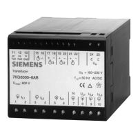
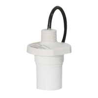
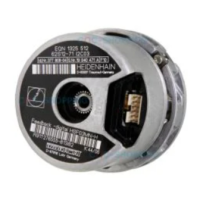
Receiver
Setting Transmission/reception using DIP S2-7 (see Table 2-5)
•
If the supply voltage fails, the alarm relay M1 drops out.
•
If the transmitter receive no signal, the fault indicator is lit continuously (red LED: ERR) and the alarm
relay M1 drops out
Data Transmission
The optical interface uses positive logic (light idle state: OFF). Incoming light is treated as active = 1 (high). To
adapt to systems that use negative logic, one switch is integrated in the transmitter and one in the receiver,
allowing them to be set to negative logic (see Table 2-4). Delivery is carried out using positive logic (light idle
state: OFF).
Overview
1.1 Scope of Application
Accessories, Binary signal transmitter 2-channel, Manual 11
C53000-G9050-C607-1, Edition 09.2019
 Loading...


