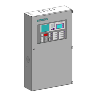
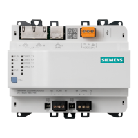
Operating Manual of FC18 Controller
Page: 9/63
2. CONNECTION DIAGRAM
Fig. 2-2 Terminal line
Note: In loop mode, wires from BP1 must end at AP1; wires from BS1 must end at AS1. The connection of field
devices (except FDCL181 isolator) is polarity free.
Fig. 2-3 Line card connection diagram (the same for Line 2)
Fig. 2-4 FRT/Mimic driver connection diagram
Note: Ensure positive and negative connections are properly in place; FC18-BUS is polarity sensitive.
Connect a 120Ω resistor as monitoring resistor. It must be connected to the end of the line. ( It can be set by
the two-digit Dip-switch on the main board, see “Dip-switch connection configuration” )
Fig. 2-5 Network connection diagram
Visible and
audible device
FC18
To NAC
NAC+
NAC-
Red
Black
Orange
Black
20K
resistor
NAC-EOL-FC18
Fig. 2-6 NAC connection diagram
 Loading...


