Operating Manual of FC18 Controller
Page: 10/63
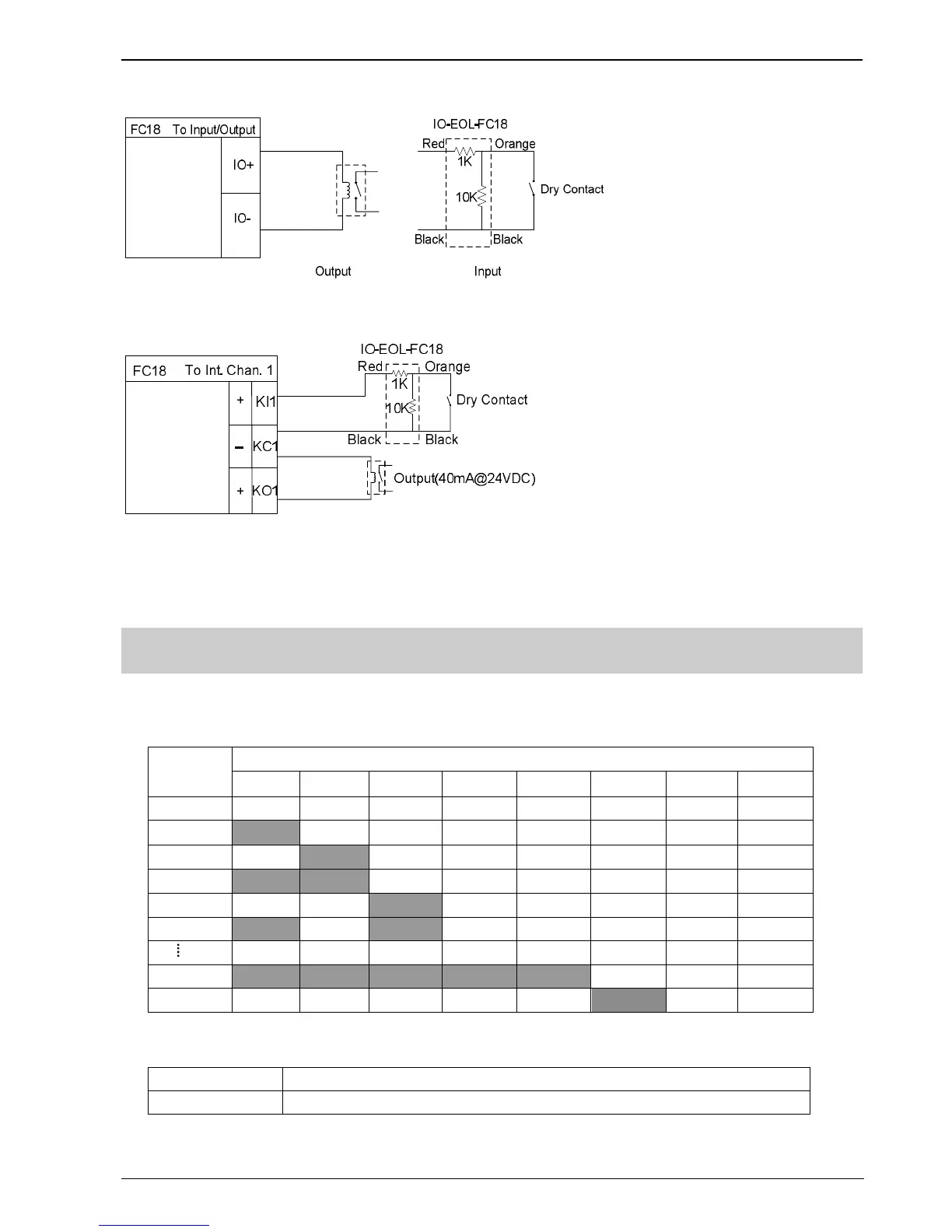
Fig. 2-7 Main board input/output connection diagram
Fig. 2-8 Interlocking panel connection diagram (the same for other channels)
Note: the load range of each output is 24VDC, 600Ω – 1.2kΩ
3. DIP-SWITCH
Each controller/interlocking panel has an eight-digit Dip-switch for address setting. Each Dip-switch can set address
1-32 within its first 6 digits.
FC18-BUS
address
DIP switches
1 2 3 4 5 6 7 8
Idle Off Off Off Off Off Off Off Off
1
On
Off Off Off Off Off Off Off
2 Off
On
Off Off Off Off Off Off
3
On On
Off Off Off Off Off Off
4 Off Off
On
Off Off Off Off Off
5
On
Off
On
Off Off Off Off Off
31
On On On On On
Off Off Off
32 Off Off Off Off Off
On
Off Off
The controller has a two-digit Dip-switch for setting terminal resistor of FC18-BUS or FR18-BUS.
1
On:FC18-BUS terminal selected; Off:not selected
2
On:FR18-BUS terminal selected; Off:not selected