Mounting and installation
2
Line and motor connections
13
Siemens AG
CM2G5111en
2014-05-16
Diagram Cable type Dimensions
A B C D
B
C
D
0.39 inches 1.96 inches 0.39 inches 1.57 inches
FSC power cables 10 mm
0.39 inches
50 mm
1.96 inches
- 70 mm
2.75 inches
FSC motor cables 10 mm
0.39 inches
50 mm
1.96 inches
10 mm
0.39 inches
40 mm
1.57 inches
FSA - FSC
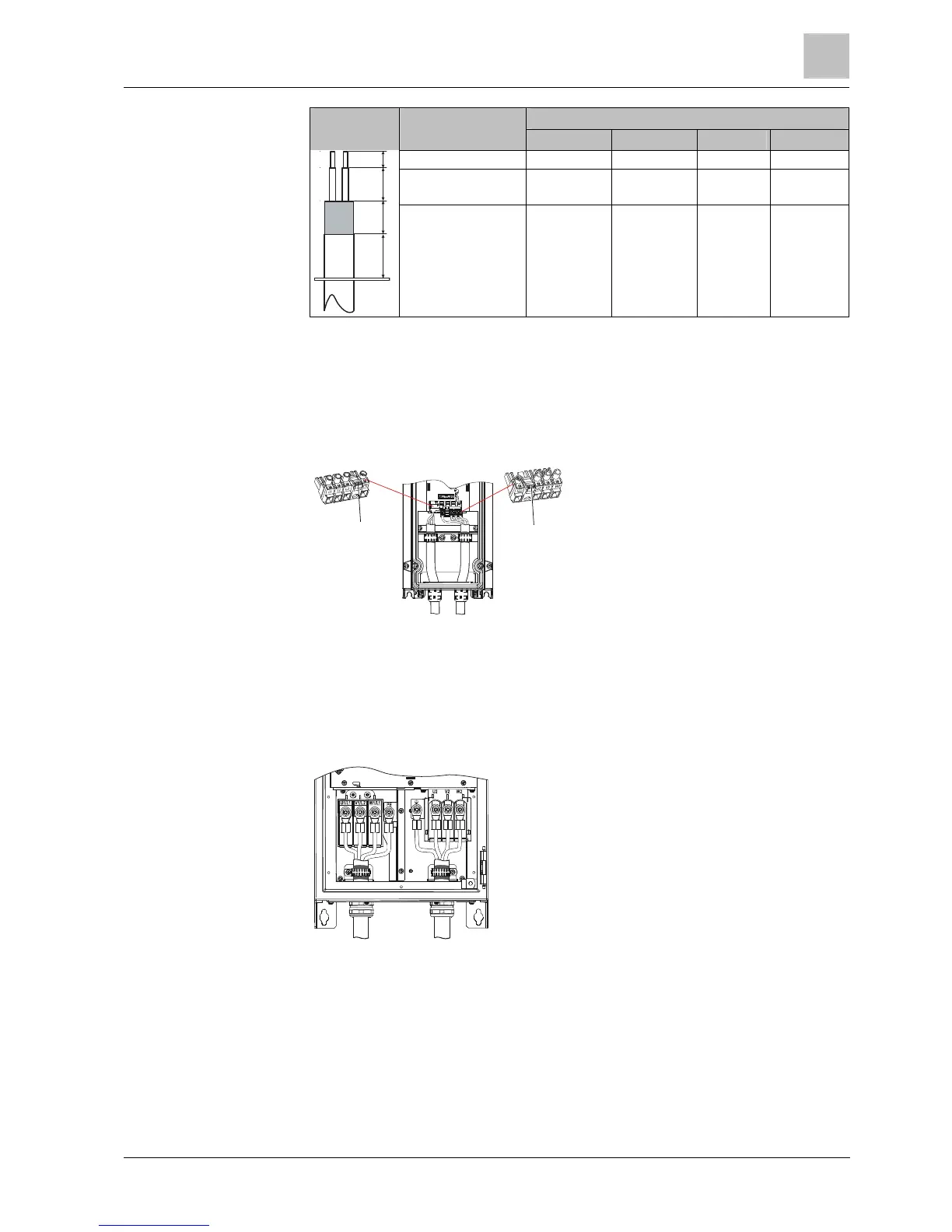
The following diagram shows the arrangement of the line and motor terminals on
the Power Module of frame sizes FSA to FSC. The tightening torques for the
terminals are indicated in the diagram.
2
2
4
5
1. Detachable current connection
2. Connector-disengaging device
3. Connection of supply voltage
4. Motor connection
5. Detachable motor connector
FSA: 0.5 Nm (4.4 lbf.in)
FSB: 0.6 Nm (5.3 lbf.in)
FSC: 1.5 Nm (13.3 lbf.in)
FSD- FSF
The following diagram shows the arrangement of the line and motor terminals on
the Power Module of frame sizes FSD to FSF. The tightening torques for the
terminals are indicated in the diagram.
12
1. Connection of supply voltage
2. Motor connection
FSD: M6: 6 Nm (53.0 lbf.in)
FSE: M6: 6 Nm (5.3 lbf.in)
FSF: M8: 13 Nm (115 lbf.in)
2.6.1.2
2.6.1.3

 Loading...


