2
Mounting and installation
Line and motor connections
12
Siemens AG CM2G5111en
2014-05-16
- Attach a ferrite core to the motor cable (only class B filter variants)
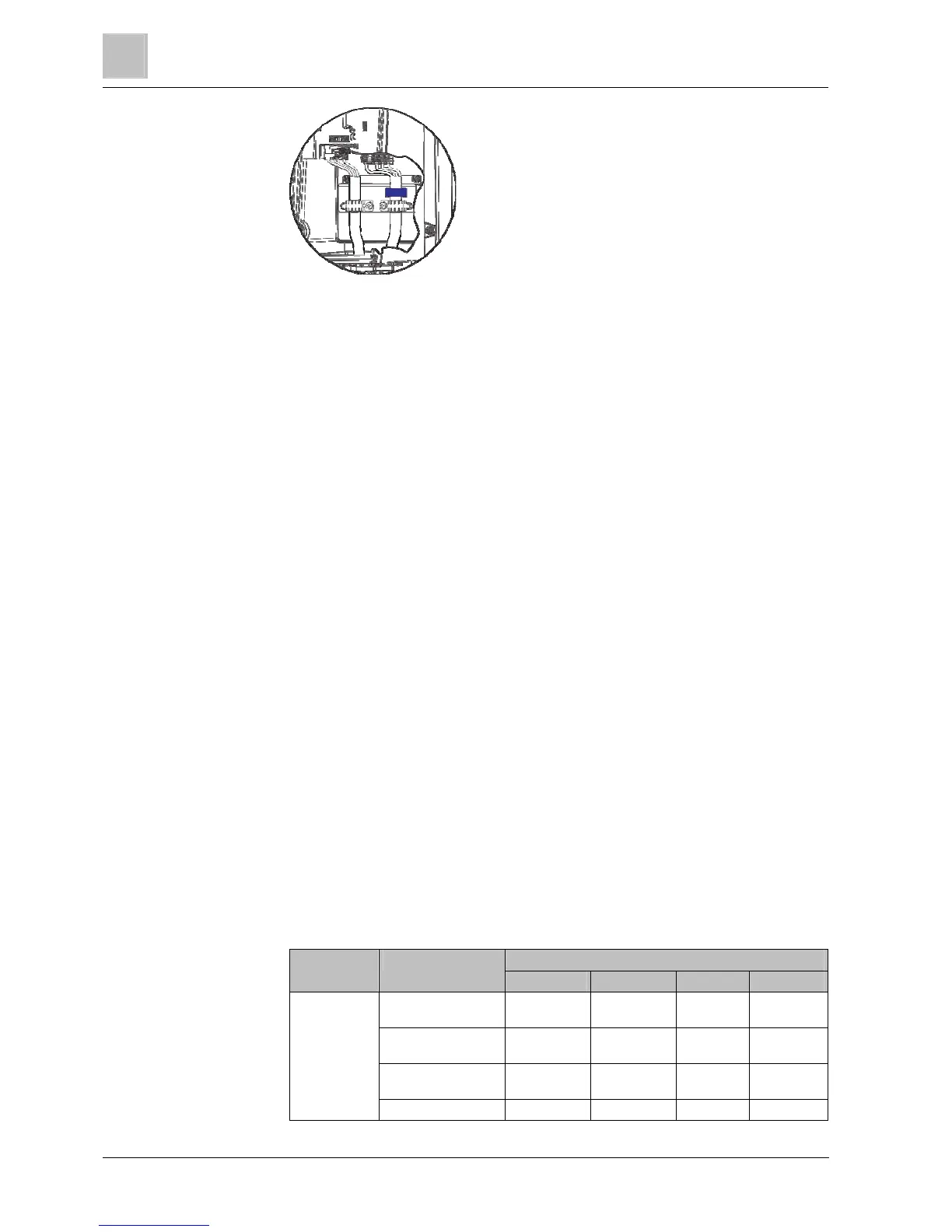
- Attach the power and motor cable to the terminals of the Power Module.
- Ensure that the cables are correctly secured through the shielding
terminals.
5. Fasten the gland plate
- Press the gland plate against the underside of the Power Module.
- Ensure that the cables are pulled through the cable glands. This prevents
excess lengths of cable inside the Power Module enclosure.
- Tighten the gland plate applying a maximum tightening torque of 2 Nm
(17.7 lbf.in).
- Check whether the seals are correctly seated; otherwise, it will not have
IP55 degree of protection.
- Tighten the cable glands applying a maximum tightening torque of 2.5 Nm
(22.12 lbf.in).
- Insert rubber grommets into all the holes of the gland plate which are not
occupied by cables.
Line and motor connections
IP55
Cable preparation
In order to achieve EMC category C1 in devices with an EMC filter of class B, the
shield must not only be exposed around the length C, it must also be exposed
when it is fed through the base plate (see outline, at the end of "D") and must be
fed conductively through the EMC cable gland.
No shielding dimensions are indicated for the input power cables because they are
generally unshielded cables. The table below helps with correctly preparing the
cables for line and motor terminals.
Diagram Cable type Dimensions
A B C D
FSA power cables 10 mm
0.39 inches
60 mm
2.36 inches
- 90 mm
3.54 inches
FSA motor cables 10 mm
0.39 inches
60 mm
2.36 inches
10 mm
0.39 inches
60 mm
2.36 inches
FSB power cables 10 mm
0.39 inches
60 mm
2.36 inches
- 50 mm
1.96 inches
FSB motor cables 10 mm 50 mm 10 mm 40 mm
2.6
2.6.1
2.6.1.1

 Loading...


