2
Mounting and installation
Wiring sequence for IP55
10
Siemens AG CM2G5111en
2014-05-16
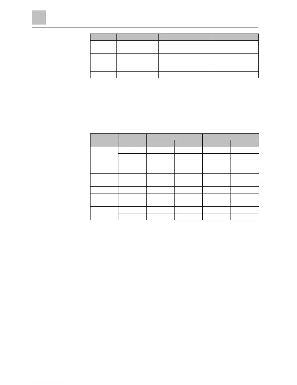
PM230 Cable type EMC category Max. cable length
Shielded C3 50 m (164 ft)
Unshielded None 100 m (330 ft)
Filter B Shielded C1 (conducted only) 25 m (80 ft) with IP54
50 m (164 ft) with IP20
Shielded C2 50 m (164 ft)
Unshielded None 100 m (330 ft)
1. You may only use copper wire of class 1, 75°C (for compliance with the UL in
frame sizes A to C).
2. Ensure that the appropriate circuit breakers or fuses with the specified current
rating are connected between the power supply and the drive.
Cable cross-sections
Frame size Power Cable cross-section Tightening torques
kW mm
2
AWG Nm lbf in
FSA 0.37...1.5 1.0 … 2.5 18…14 0.5 4.4
2.2...3 1.5…2.5 16…14 0.5 4.4
FSB 4 2.5…6.0 14…10 0.6 5.3
5.5...7.5 4.0…6.0 12…10 0.6 5.3
FSC 11 6.0 … 16 10 … 5 1.5 13.3
15...18.5 10 … 16 7 … 5 1.5 13.3
FSD 22.0...30 10...35 5...2 6 53
FSE 37 25...50 3...2 6 53
45 35...50 2...4/0 6 53
FSF 55 70...120 2/0...4/0 13 115
75...90 95...120 3/0...4/0 13 115
Cable cross-section of the grounding conductors
The material of the protective grounding conductor must be the same as the
material of the power cable. If this is not the case, the specific resistance of the
protective grounding conductor must not be higher than the specific resistance of
the power cables. The relevant diameter of the power cables is the diameter of the
line supply cable, and not the diameter of the motor cables.
In the case of power cables up to 35 mm
2
, the ground cable must have a cross-
section of at least 10 mm² (16 mm² Al).
It is always advisable to use a 16mm
2
Cu equipotential bonding conductor at least.
For power cables with a diameter of more than 35 mm
2
, the protective grounding
conductor must have at least half of the size of the cross-section of the power
cable.
Wiring sequence for IP55
The requirements and actions for wiring the Power Module correctly are described
below.
2.4.2
2.5

 Loading...


