2
Mounting and installation
Dimension drawings of the PM230
8
Siemens AG CM2G5111en
2014-05-16
Mounting and installation
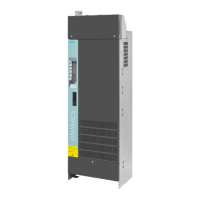
Dimension drawings of the PM230
You can find the dimension drawings in the enclosed document, "Getting Started
SINAMICS PM230".
Structure of the Control Unit
1
2
3
6
5
4
8
9
10
11
1
5
2
3
4
10
8
6
7
9
9
10
11 11
1 5
1 5
1 8
6 9
5 1
9 6
Voltage
Memory card slot (MMC or SD card)
DIP switch for AI0
and AI1 (terminals
3/4 and 10/11)
LG-NI1000 DIP switch AI2
( /)terminals 50 51
Interface for an operator panel (IOP or BOP-2)
Digital outputs
Current
Terminal designation
Terminal strip
USB interface for STARTER
Status LED
Not assigned
CAN_L, CAN signal (dominant low)
Not assigned
Not assigned
CAN_H, CAN signal (dominant high)
(GND), optional ground
(CAN _SHLD), optional shield
Not assigned
CAN_GND, CAN ground
SUB-D connector for
CANopen
DIP switch for fieldbus address
( )for PROFINET no function
Pin
0 V, reference potential
RS485P, receive and send (+)
Not connected
Cable shield
RS485N, receive and send (-)
Pin
Shield, ground connection
Not assigned
DGND, reference potential for data
(C/C’)
VP, supply voltage
Not assigned
RxD/TxD-N, receive and send (A/A’)
Not assigned
CNTR-P, control signal
RxD/TxD-P, receive and send (B/B’)
Pin
Switch for bus terminating resistor
Current
Pin
TX+. Transmit data +
TX-, transmit data -
Not assigned
RX-, receive data -
Not assigned
Not assigned
Not assigned
RX+, receive data +
Connector for the
RS485 interface
SUB-D socket for
PROFIBUS DP
RJ45 connector socket
for PROFINET IO
Example:
Address = 10
AI0
AI1
OffOn
Bit 0 (1)
Bit 1 (2)
Bit 2 (4)
Bit 3 (8)
Bit 4 (16)
Bit 5 (32)
Bit 6 (64)
RDY
BF
---
LNK1, nur bei PROFINET
LNK2, nur bei PROFINET
31 +24V IN
32 GND IN
-
35 +10V OUT
36 GND
50
AI 2+/NI1000
51 GND
52
AI 3+/NI1000
53 GND
-
-
-
-
10 AI 1+
11 AI 1-
26 AO 1+
27 GND
1+10V OUT
2GND
3AI 0+
4AI 0-
12 AO 0+
13 GND
21 DO 1 NO
22 DO 1 COM
14 T1 MOTOR
15 T2 MOTOR
9+24V OUT
28 GND
69 DI COM
5DI 0
6DI 1
7DI 2
8DI 3
16 DI 4
17
1
2
3
4
12
13
21
22
18
19
23
24
20
14
15
9
28
69
5
6
7
8
16
17
DI 5
Analog In/OutAnalog In/Out
31
32
35
36
50
51
52
53
10
11
26
27
Analog In/OutDigital In/Out
25
18DO 0 NC
19DO 0 NO
20
DO 0 COM
23DO 2 NC
24DO 2 NO
25
DO 2 COM
1
2
3
4
5
1
2
3
4
5
6
7
8
1
2
3
4
5
6
7
8
9
1
2
3
4
5
6
7
8
8
2
NI1000
L
G
-
2
2.1
2.2

 Loading...


