Fault rectification
6
Hardware diagnostics
55
Siemens AG
CM2G5111en
2014-05-16
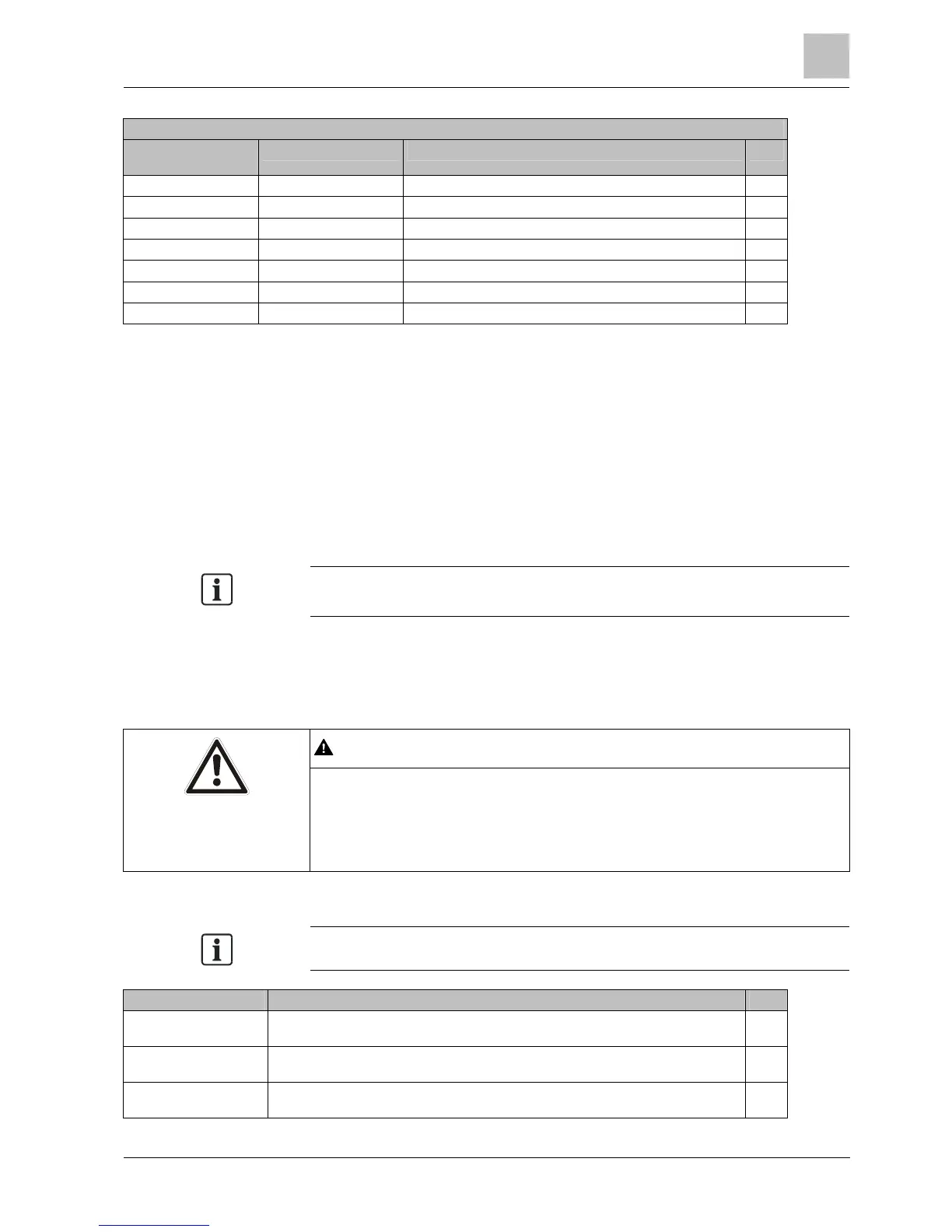
IGBT bridge test
Positive measuring
point
Negative measuring point Expected result OK
U DC+ Diode aperture – typically 0.3...0.5 V
V DC+ Diode aperture – typically 0.3...0.5 V
W DC+ Diode aperture – typically 0.3...0.5 V
U DC Diode block – OL/High impedance
V DC Diode block – OL/High impedance
W DC Diode block – OL/High impedance
Procedure
If the drive fails any of these tests:
Remove the power unit in order to replace or repair it.
If a short-circuit occurs at the input rectifiers or at components of the IGBT
bridge:
Check the state of fuses in the supply line, of contactors, disconnectors or of
the motor itself.
Please be aware that an apparently open circuit can also occur following a
component short-circuit and the resulting strong flow of current.
Power test
DANGER
Electrical current and moving parts when commissioning equipment or systems
● Before commissioning the drive, secure the system, for example by cordoning
it off.
● Ensure that all the covers are applied to the drive, and that no live parts are
accessible.
Wherever possible, connect measuring equipment before switching the drive on.
Check/Test Description OK
Measuring DC bus
voltage
The measured DC voltage at the terminals (not available on all types) should correspond
to the peak-to-peak voltage of the applied AC input (typically 580 V).
DC bus voltage – from
parameter r0070
r0070 is the measured DC bus voltage of the drive. This does not function below 200 V
DC. The parameter has access level 3.
DC bus voltage – from
parameter r0026
r0026 is the measured, smoothed DC bus voltage of the drive. This does not function
below 200 V DC. The parameter has access level 2.
6.4.2

 Loading...


