Mounting and installation
2
Terminal strips in the Control Unit
9
Siemens AG
CM2G5111en
2014-05-16
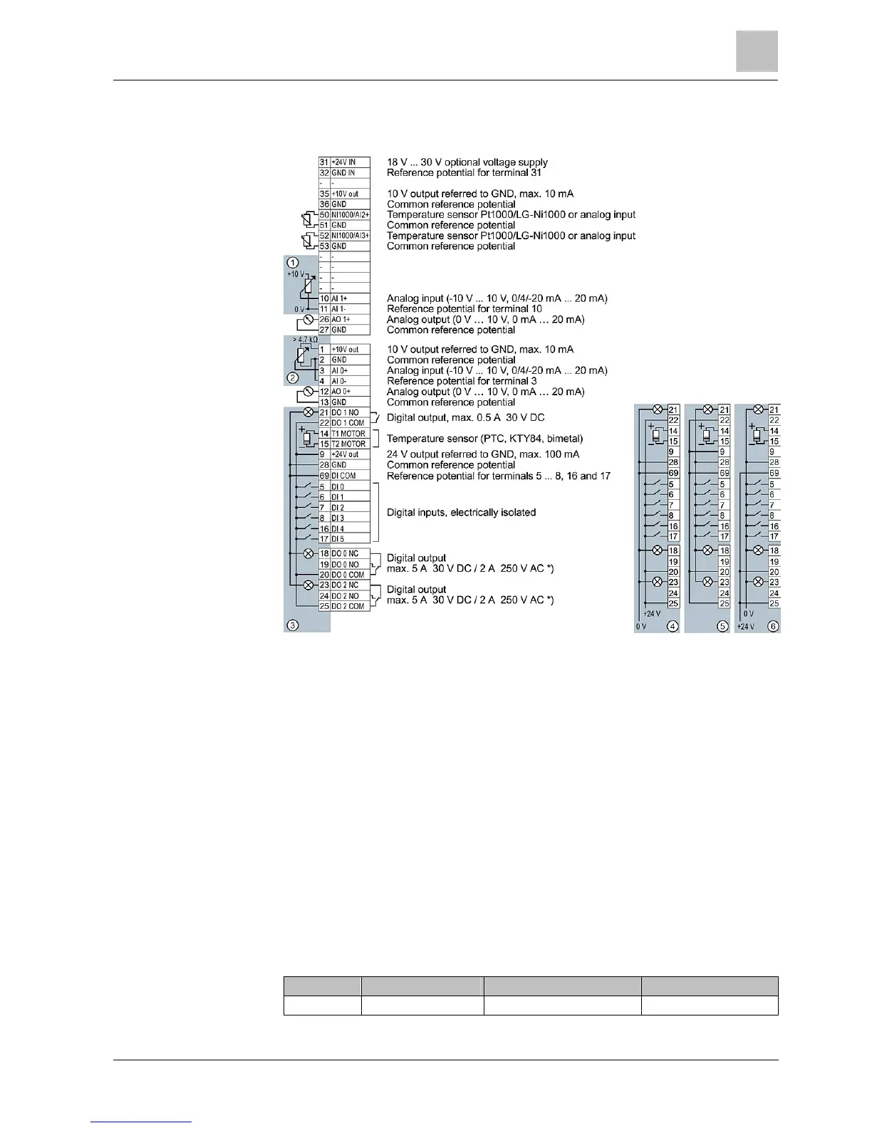
Terminal strips in the Control Unit
The wiring of the terminal strip is displayed by way of an example for every type of
terminal.
If more than 6 digital inputs are required, use terminals 3 and 4 (AI 0) or terminals
10 and 11 (AI 1) as additional digital inputs DI 11 or DI 12.
1. Wiring when using the internal power supplies
DI = high if the switch is closed
2. Wiring when using the external power supplies
DI = high if the switch is closed
3. Wiring when using the internal power supplies
DI = low if the switch is closed
4. Wiring when using the external power supplies
DI = low if the switch is closed
Motor cable lengths and cross-sections
Cable specifications for conformity with EMC requirements
PM230 Cable type EMC category Max. cable length
Filter A Shielded C2 25 m (80 ft)
2.3
2.4
2.4.1

 Loading...


