2
Mounting and installation
EMC directives
18
Siemens AG CM2G5111en
2014-05-16
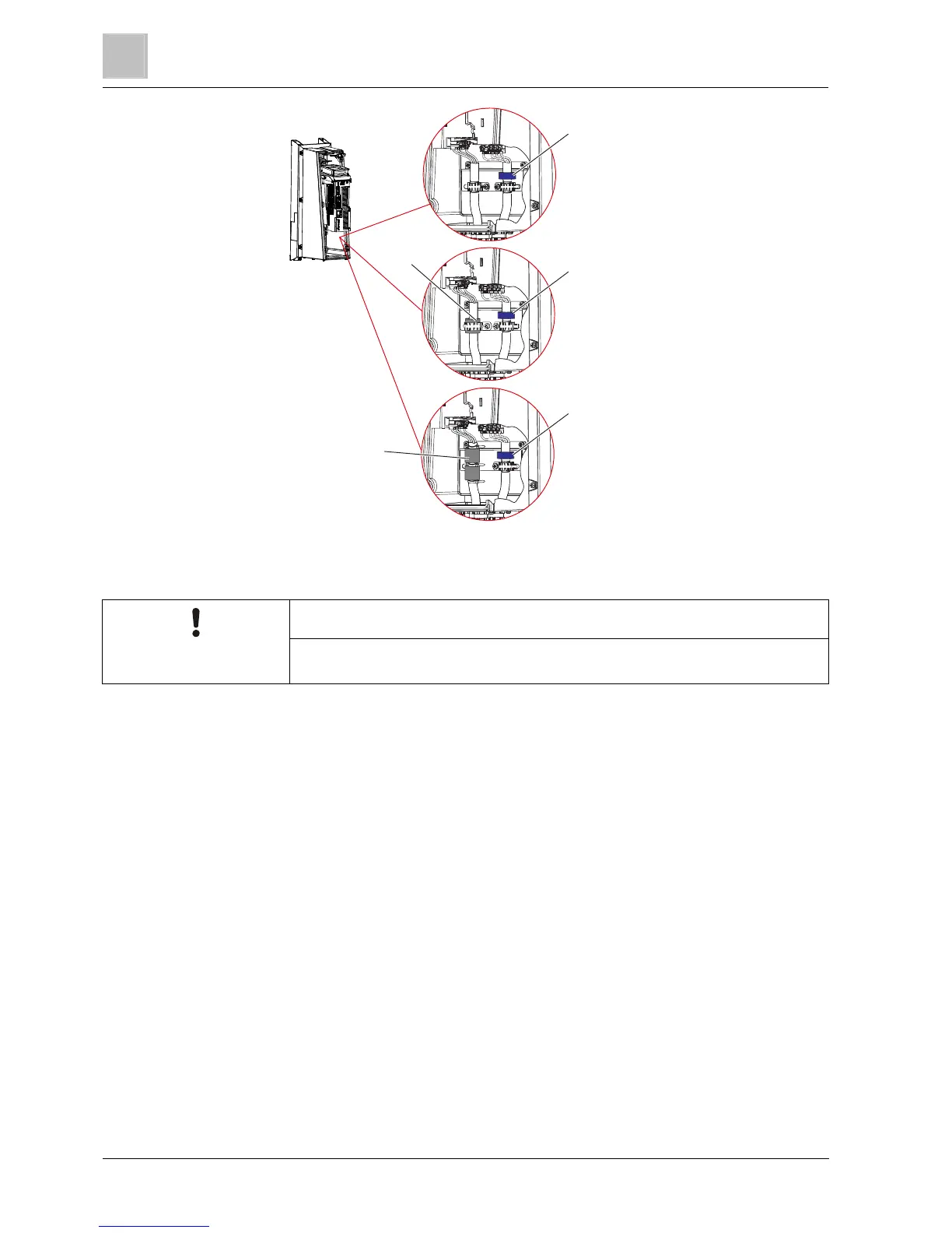
ferrite ring
ferrite ring
ferrite ring
Gray ferrite ring
1 x ferrite ring
1 x large cable clamp
Gray ferrite rings
2 x ferrite rings
3 x cable ties
FSA (0.37 kW ... 3.0 kW)
FSB (4.0 kW ... 7.5 kW)
FSC (11.0 kW ... 15.0 kW
Colored
Colored
Colored
IP20
NOTICE
● Only install and operate IP20 degree of protection drives in a closed control
cabinet.
Equipment design
The drives are designed for operation in industrial environments where high values
of electromagnetic interference are reached. Safe, reliable and disturbance-free
operation is only ensured if the control cabinet is professionally installed.
Connect all the metallic parts of the control cabinet (side plates, rear panels,
top and base plates) to the frame of the cabinet with good electrical
conductivity. Make the connections as two-dimensional as possible or establish
them using a large number of point-like screw connections
Connect the PE bar and the EMC shield bar to the control cabinet frame
through a good electrical connection established through a large surface area
Connect all the metal enclosures of the devices and supplementary
components installed in the cabinet – e.g. drive or line filter over a large area
and with good conductivity. It is best to mount these devices and
supplementary components on a mounting plate which is bright and offers
good conductivity. Connect them, in turn, to the control cabinet frame and, in
particular, to the PE bar and EMC shield bar over a large area and with good
conductivity
Follow the instructions in section EMC directives [➙ 15] "Connections and
interference suppression"
2.7.2
2.7.2.1

 Loading...


