Fault rectification
6
Restart after a crash
47
Siemens AG
CM2G5111en
2014-05-16
Fault rectification
The variable speed drive uses the following means to display faults and operating
states:
The LEDs on the front indicate the most important operating states.
The drive displays alarms and faults via the fieldbus, the terminal strip, a
connected operator panel, or via the STARTER software.
larms and faults have a unique number.
Restart after a crash
The drive can adopt the following state, for example, by loading a defective file
from the memory card:
The motor is switched off.
You cannot communicate with the drive, either via the operator panel or other
interfaces.
1. Remove the memory card if one is inserted in the converter.
2. Switch off the drive power supply.
3. Wait until all LEDs on the drive are extinguished.
4. Switch on the power supply again.
5. Repeat steps 2 to 4 until fault code F01018 is output.
6. Repeat steps 2 to 4 once again until fault code F01018 is output.
The drive adopts the factory settings.
Repeat the commissioning process.
Displayed operating states
The Control Unit has two LEDs which indicate the operating state of the drive:
LED RDY = Ready
LED BF = Bus Fault
The LED RDY (Ready) is temporarily orange after the power supply voltage is
switched on. As soon as the color of the LED RDY changes to either red or green,
the LEDs signal the drive state.
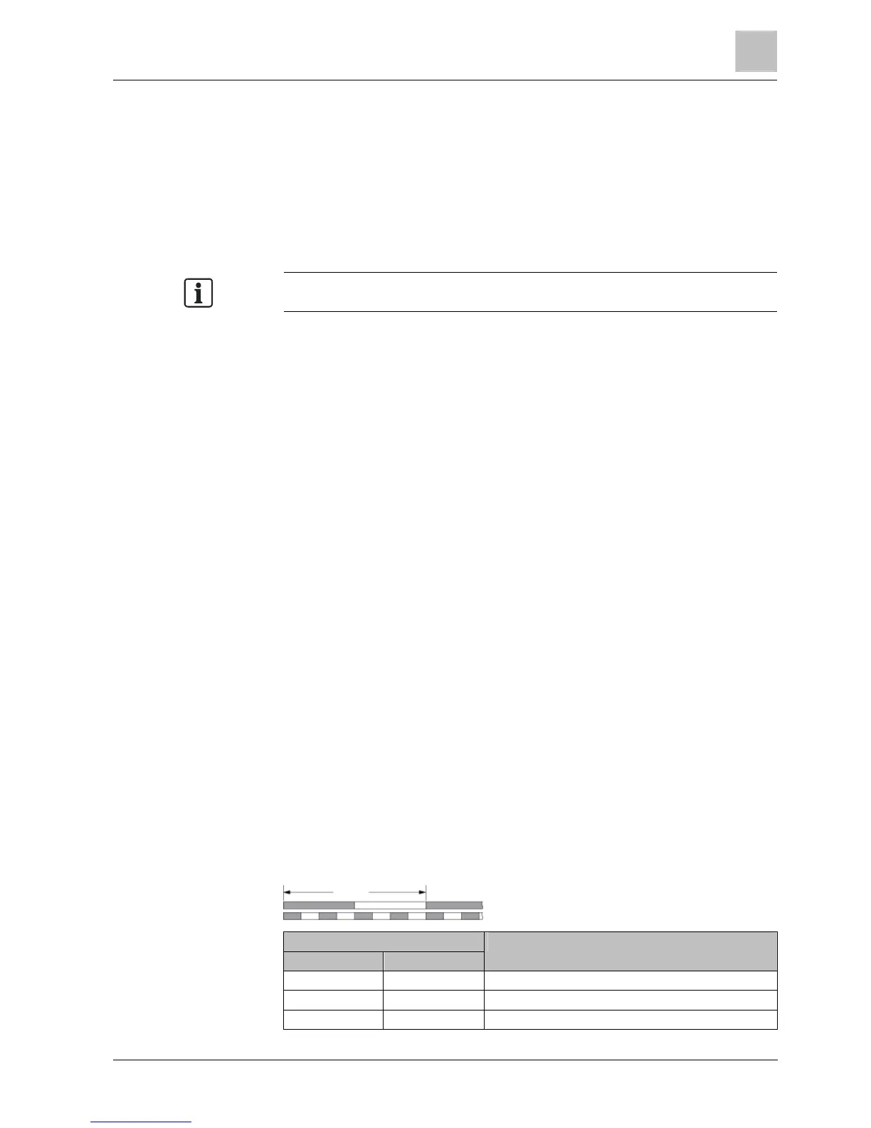
In addition to the signal states "On" and "Off" there are two different flashing
frequencies:
Rapid flashing
Slow flashing
2 s
LED Description
RDY BF
Green - On --- No fault
Green – Slow --- Commissioning or reset to factory settings
Red – Fast --- No fault
6
6.1
6.2

 Loading...


