Accessing the connection compartment through the rear
110-0134.9 / 14 NXAIR / ≤ 40 kA 355
Procedure
Installation of the rear wall is described hereafter by the example of a 3-panel arrangement.
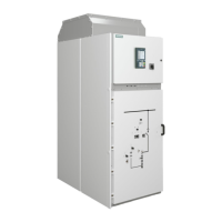
Fig. 654: All panel versions except for contactor
panels with panel width 435 mm:
Rear wall, 3-panel arrangement
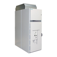
Fig. 655: Contactor panels with panel width
435 mm only:
Rear wall,
3-panel arrangement
All panel versions except for contactor panels with panel width 435 mm and switch-
disconnector panel:
At the rear side of the panel, insert the rear wall (1) by the handle, and push it down.
Fix the rear wall by screwing the bolts at the bottom hand-tight:
• 4 bolts M8x20 with contact washers (2)
Tighten the bolts with a tightening torque of 25 Nm.
Fig. 656: All panel versions except for contactor panels with panel width 435 mm and
switch-disconnector panel: Inserting and fixing the rear wall

 Loading...


