Installation
128/293 Revision 11 • INSTALLATION AND OPERATING INSTRUCTIONS • NXPLUS C • 802-9081.9
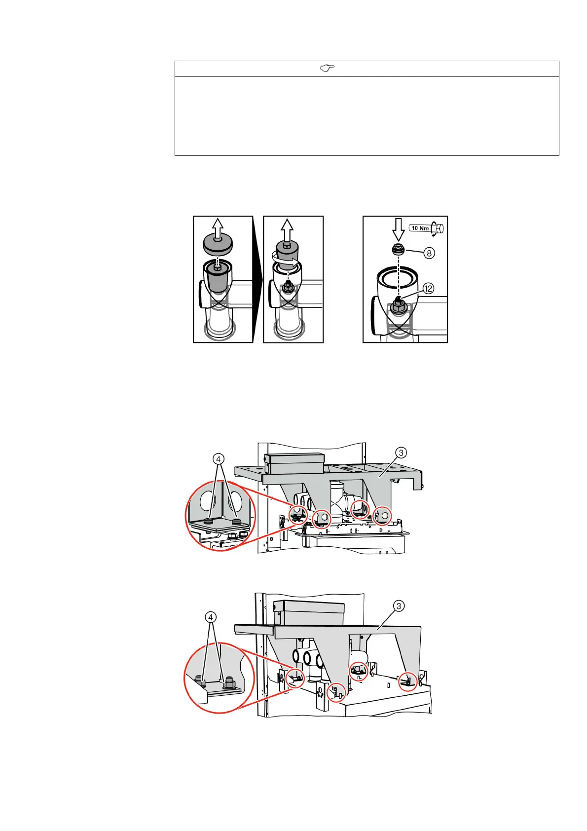
➭ Remove the cap and the screw-type cone of end adapter / cross adapter.
➭ Screw the centering nut ⑧ onto the threaded stud ⑫ in the end adapter / cross adapter
(tightening torque: 10 Nm).
➭ Set the voltage transformer frame ③ down on the switchgear with the protrusion aligned
to the left.
- Circuit-breaker panel of 450 mm and auxiliary transformer panel: The holes in the
frame feet must match with the holes of the switchgear.
- Other panel types: The threaded studs on the switchgear vessel must fit into the holes of
the frame feet.
➭ Depending on the panel type, fasten the voltage transformer frame ③ using nut-and-
washer assemblies or bolts ④ .
INFORMATION
To mount the voltage transformer on the busbar, the caps and screw-type cones of the busbar
are not required.
➭ Mount the busbar according to the installation instructions (see page 111, "Assembling the
busbars"); do not mount caps and screw-type cones.
➭ If the busbar is already mounted, remove the caps and screw-type cones again.
➭ Put unneeded components into the storage box.
Fig. 90: Removing the cap and the
screw-type cone
Fig. 91: Screwing on the centering
nut
 Loading...


