802-9081.9 • INSTALLATION AND OPERATING INSTRUCTIONS • NXPLUS C • Revision 11 53/293
Description
A coupling magnet, which is fitted to the bottom end of the measurement box, transmits its
position to an armature outside the switchgear vessel through the non-magnetizable
switchgear vessel (magnetic coupling). This armature moves the ready-for-service indicator at
the operating front of the panel.
While changes in the gas density during the loss of gas, which are decisive for the dielectric
strength, are displayed, changes in the relative gas pressure resulting from temperature and
external pressure variations are not. The gas in the measurement box has the same
temperature as that in the switchgear vessel.
The temperature effect is compensated via the same pressure change in both gas volumes.
9.12 Interlocks
• The three-position switch is equipped with a mechanical interlock. This interlock prevents
the circuit-breaker from being closed while the three-position switch is being operated.
Furthermore the mechanical interlock prevents the three-position switch from being
operated while the circuit-breaker is closed.
• The switching gate prevents switching straight from CLOSED to READY-TO-EARTH or from
READY-TO-EARTH to CLOSED, as the operating lever must be replaced and re-inserted in the
OPEN position.
• The control gate of the switching gate of the three-position switch can be padlocked in all
three switch positions. Control gate lever on the left: the three-position (switch-
)disconnector can be operated, in the center: switching operations are not possible, on the
right: ready-to-earth/earthing is possible.
• Interlocking between feeder locking device and three-position disconnector (circuit-breaker
only lockable in earthed position)
• Interlocking between feeder locking device, three-position disconnector and cable
compartment cover (circuit-breaker only lockable in earthed position, cable compartment
cover only removable in earthed position)
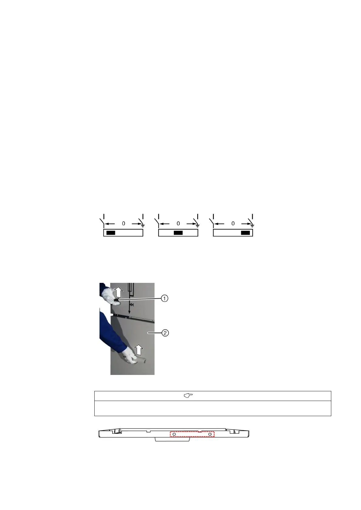
• To do this, lift the interlocking lever ① and remove the cable compartment cover ② .
Fig. 28: Coding of cable compartment cover for 600 mm panel without fuses (view from
above)
INFORMATION
To avoid mixing up, the cable compartment covers of panels with a width of 600 mm are
marked with different holes.