Installation
134/293 Revision 11 • INSTALLATION AND OPERATING INSTRUCTIONS • NXPLUS C • 802-9081.9
15.11 Installing the horizontal pressure relief duct
Panel versions with horizontal pressure relief duct
Modular design
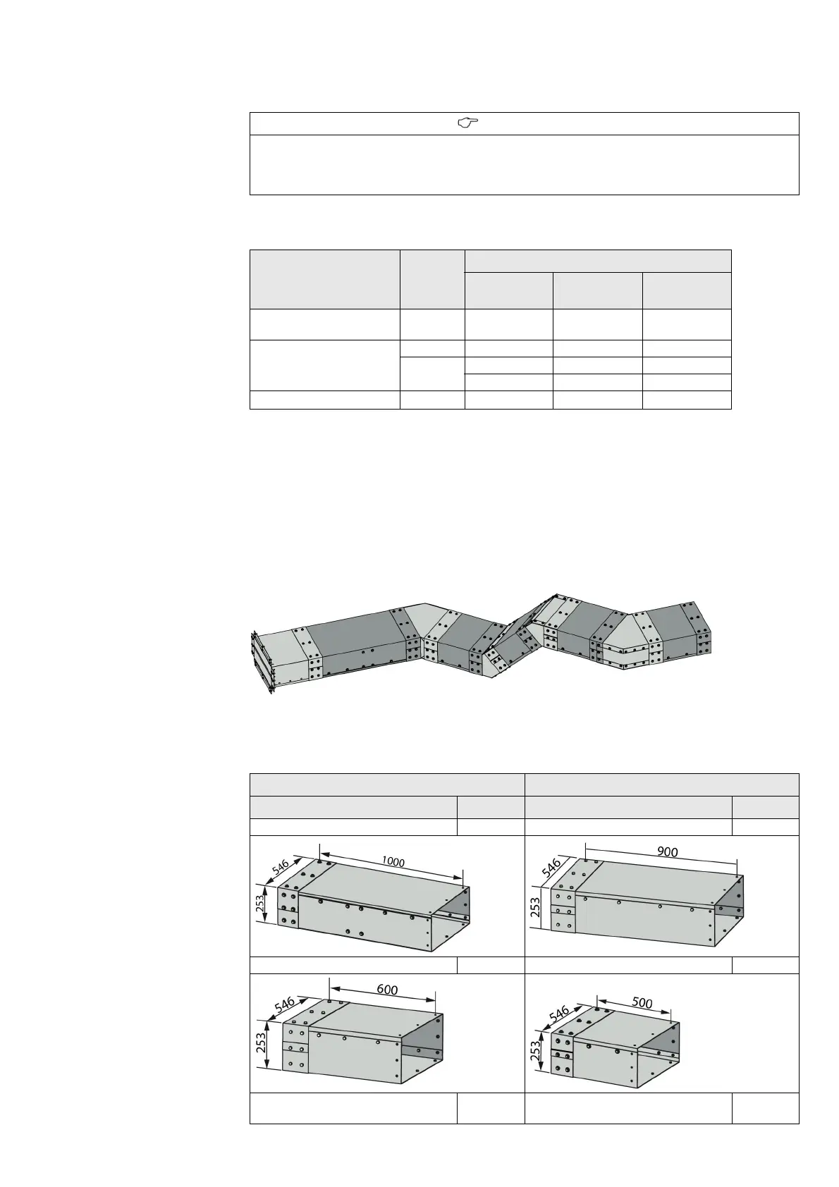
The evacuation duct can be set up with modular elements from the switchgear up to the
opening in the substation wall.
The individual elements can be combined at will in order to build an evacuation duct matching
with the switchgear arrangement situation in the substation.
Fig. 101: Possible combinations of evacuation duct elements
Duct elements
INFORMATION
If a horizontal pressure relief duct is installed, the busbar cover is not assembled.
➭ Install the switchgear termination, see page 143, "Installing the switchgear termination".
➭ Install the horizontal pressure relief duct.
Design option Panel
width
[mm]
Busbar current depending on the panel position
1
1
Independently from the panel position, the panel types LS/LLK(2000 A/2500 A), EB
and aME are always equipped with ventilation.
Left end panel Intermediate
panel
Right end panel
Standard (without
ventilation)
600/450 - ≤ 1250 A -
With ventilation 600/450 ≤ 1250 A - ≤ 1250 A
900
2000 A 2000 A 2000 A
2500 A 2500 A 2500 A
Evacuation at the rear 600/450 -
≤ 1250 A
2
2
Only for a panel width of 600 mm.
-
Duct element Duct element
Designation Length Designation Length
Evacuation duct 1000 mm 1000 mm Evacuation duct 900 mm 900 mm
Evacuation duct 600 mm 600 mm Evacuation duct 500 mm 500 mm
Evacuation duct 450 mm 450 mm Evacuation duct, adjustable 520 to
685 mm