Installation
158/293 Revision 11 • INSTALLATION AND OPERATING INSTRUCTIONS • NXPLUS C • 802-9081.9
➭ Screw nut-and-washer assemblies onto the studs.
Fig. 115: Example for panel width 600 mm
16.2 Connecting cable T-plugs
For NXPLUS C switchgear, only cable T-plugs shielded by means of an external semi-
conductive layer may be used as a rule. The suitable cable plugs for outside-cone bushings of
interface type C according to EN 50181 are listed in the section "Description" (see page 34,
"Cable connection"NXPLUS C).
Please select the tightening torque of the bolted joint "cable T-plug - bushing" according to the
specifications of the respective cable T-plug manufacturer.
If there are no specifications from the cable T-plug manufacturer's side, please tighten the
bolted joint with 50 Nm.
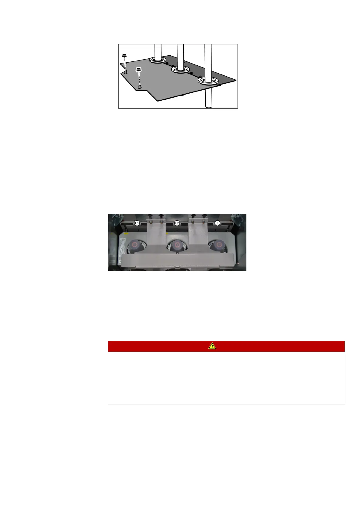
Phase sequence
Fig. 116: Phase sequence of bushings in the cable compartment
Preparations ➭ Earth the feeder.
➭ Undo the fixing bolts of the cable compartment cover.
➭ Lift the cable compartment cover and remove it to the front.
➭ Remove the floor cover (see page 155, "Removing the floor cover").
➭ Cut rubber sleeves to size (see page 156, "Cutting the rubber sleeves to size").
Mounting cable T-plugs
on cable ends
DANGER
Life-endangering high voltage
Will cause death, serious injury or considerable property damage.
Do not energize the switchgear as long as no cables or surge-proof caps are mounted.
➭ If the panel has to be live without connected cables, close the outside-cone bushings in a
surge-proof way.
➭ Mount surge-proof caps onto bushings type C (with bolted contact M16).