802-9081.9 • INSTALLATION AND OPERATING INSTRUCTIONS • NXPLUS C • Revision 11 131/293
Installation
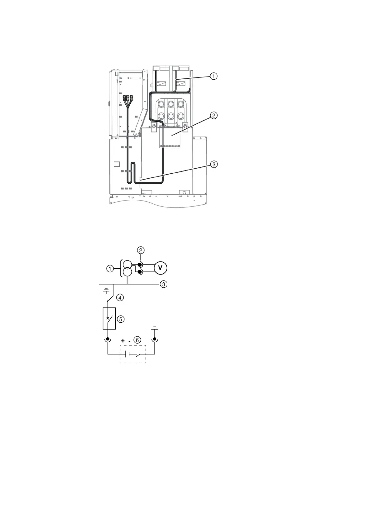
➭ Lead the secondary leads of the instrument transformers into the low-voltage
compartment, and connect them.
Observe the phase sequence!
➭ Connect the earthing cable of the end adapters/cross adapters.
Checking the voltage
transformer connection
➭ On one panel of the switchgear, switch the circuit-breaker and the three-position switch to
CLOSED position.
➭ Connect a voltmeter to the outgoing cable of the voltage transformer and set the mV-range.
➭ Apply 15 to 20 V DC to L1, L2, L3 to earth with the battery and observe the voltmeter.
✔ If the pointer moves a little bit, the voltage transformer connection is in good order.
Fig. 96: Cable routing into the low-voltage compartment
①
Secondary leads
②
Vertical wiring duct
(only for secondary leads with
steel tube)
③
Cutout
Fig. 97: Circuit diagram for checking
the voltage transformer
connection
①
Voltage transformer
②
Plug connector
③
Busbar
④
Three-position switch
⑤
Circuit-breaker
⑥
Battery box (15 – 20 V)
 Loading...


