Installation
148/293 Revision 11 • INSTALLATION AND OPERATING INSTRUCTIONS • NXPLUS C • 802-9081.9
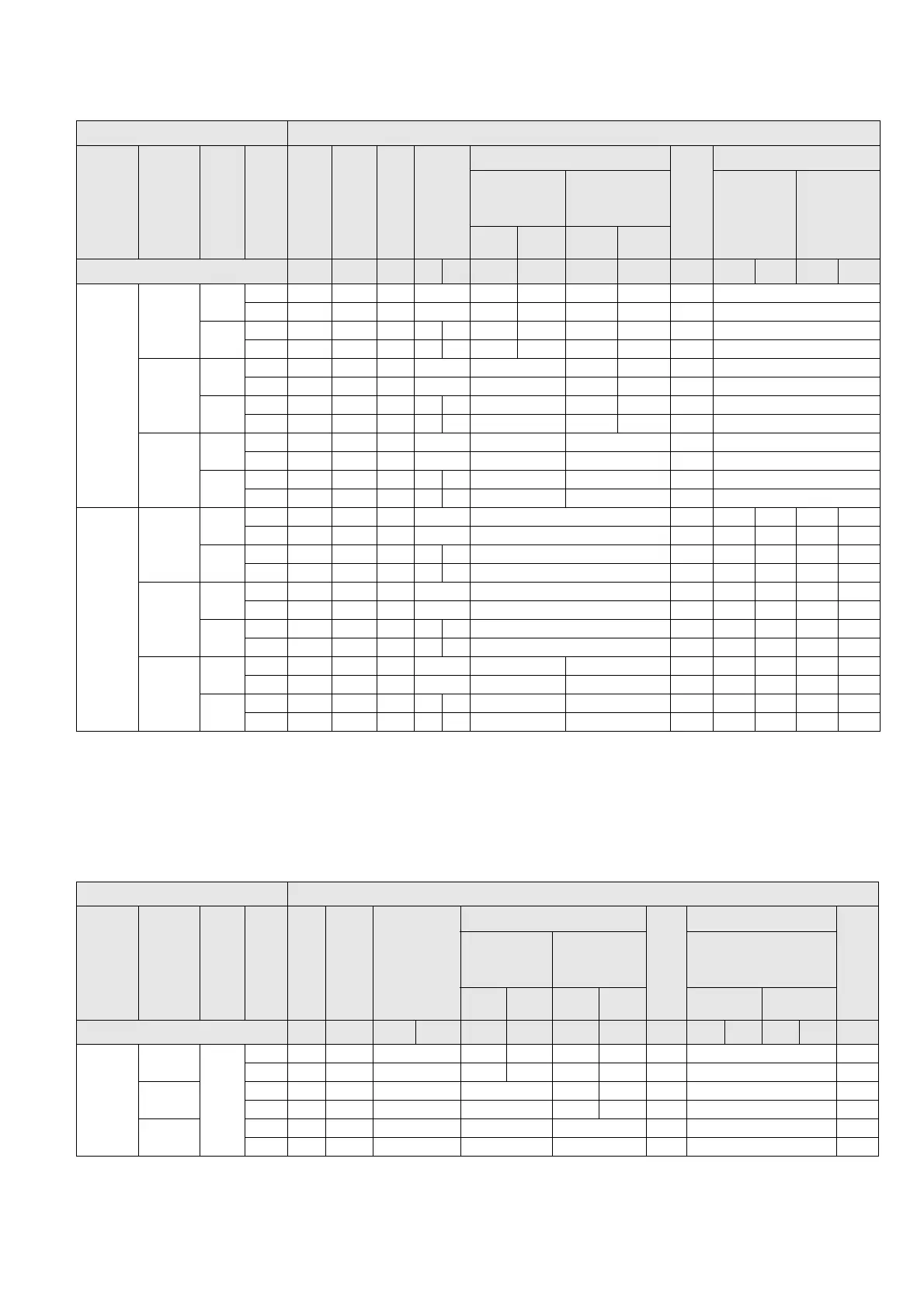
Component table 3
Component table 4
Switchgear panel Components
Panel width
[mm]
Position
Height of
LV compartment
Pressure relief
Supporting angle
1
Connection plate
2
Cover
Side wall
3
Angle plate
Reinforcing plate
Sealing angle
4
Widht of left-
hand adjacent
panel [mm]
Width of right-
hand adjacent
panel [mm]
Wall-
standing
arrangement
Free-
standing
arrangement
600 900 600 900
Number in exemplary illustration: ① ② ③ ④ ⑤ ⑥ ⑥ ⑦ ⑦ ⑧ ⑨ ⑩ ⑨ ⑩
600
Intermedi
ate panel
760
No 96 --- 03 05 24 26 25 27 10 ---
Yes --- --- 01 05 12 14 13 15 08 ---
1160
No 96 84 04 06 07 28 30 29 31 11 ---
Yes --- 84 02 06 07 18 20 19 21 09 ---
Left end
panel
760
No 96 --- 03 05 16 25 27 10 ---
Yes --- --- 01 05 16 13 15 08 ---
1160
No 96 84 04 06 07 22 29 31 11 ---
Yes -- 84 02 06 07 22 19 21 09 ---
Right end
panel
760
No 96 --- 03 05 --- 17 --- ---
Yes --- --- 01 05 --- 17 --- ---
1160
No 96 84 04 06 07 --- 23 --- ---
Yes --- 84 02 06 07 --- 23 --- ---
900
Intermedi
ate panel
760
No --- --- 57 05 41 10 97 98 99 100
Yes --- --- 57 05 41 08 97 98 99 100
1160
No --- 85/86 58 39 40 42 11 97 98 99 100
Yes --- 85/86 58 39 40 42 09 97 98 99 100
Left end
panel
760
No --- --- 57 05 41 10 97 --- 99 ---
Yes --- --- 57 05 41 08 97 --- 99 ---
1160
No --- 85/86 58 39 40 42 11 97 --- 99 ---
Yes --- 85/86 58 39 40 42 09 97 --- 99 ---
Right end
panel
760
No --- --- 36 05 --- 43 --- --- 98 --- 100
Yes --- --- 36 05 --- 43 --- --- 98 --- 100
1160
No --- 85/86 37 39 40 --- 44 --- --- 98 --- 100
Yes --- 85/86 37 39 40 --- 44 --- --- 98 --- 100
1
Only for panel with feeder current ≤ 1000 A.
2
85: For voltage transformers at the busbar in the right-hand adjacent panel.
86: For panel with voltage transformers at the busbar.
3
Mount only one left-hand or right-hand side wall each.
4
Only for left-hand or right-hand adjacent panel with a panel width of 600 mm.
Switchgear panel Components
Panel width
[mm]
Position
Height of
LV compartment
Pressure relief
Supporting angle
1
Cover
Side wall
2
Angle plate
Reinforcing plate
Sealing angle
3
Angle
Widht of left-
hand adjacent
panel [mm]
Width of right-
hand adjacent
panel [mm]
Type of installation of
the switchgear
600 900 600 900 Wall Free
Number in exemplary illustration: ① ③ ④ ⑤ ⑥ ⑥ ⑦ ⑦ ⑧ ⑨ ⑩ ⑨ ⑩ ⑪
600
Intermedi
ate panel
760
No 96 124 05 108 110 114 116 10 --- 125
Yes --- 101 05 109 112 115 117 106 --- 125
Left end
panel
No 96 124 05 113 114 116 10 --- 125
Yes --- 101 05 113 115 117 106 --- 125
Right end
panel
No 96 124 05 --- 118 --- --- 125
Yes --- 101 05 --- 118 --- --- 125