Installation
150/293 Revision 11 • INSTALLATION AND OPERATING INSTRUCTIONS • NXPLUS C • 802-9081.9
Installation for
component tables 3 and 4
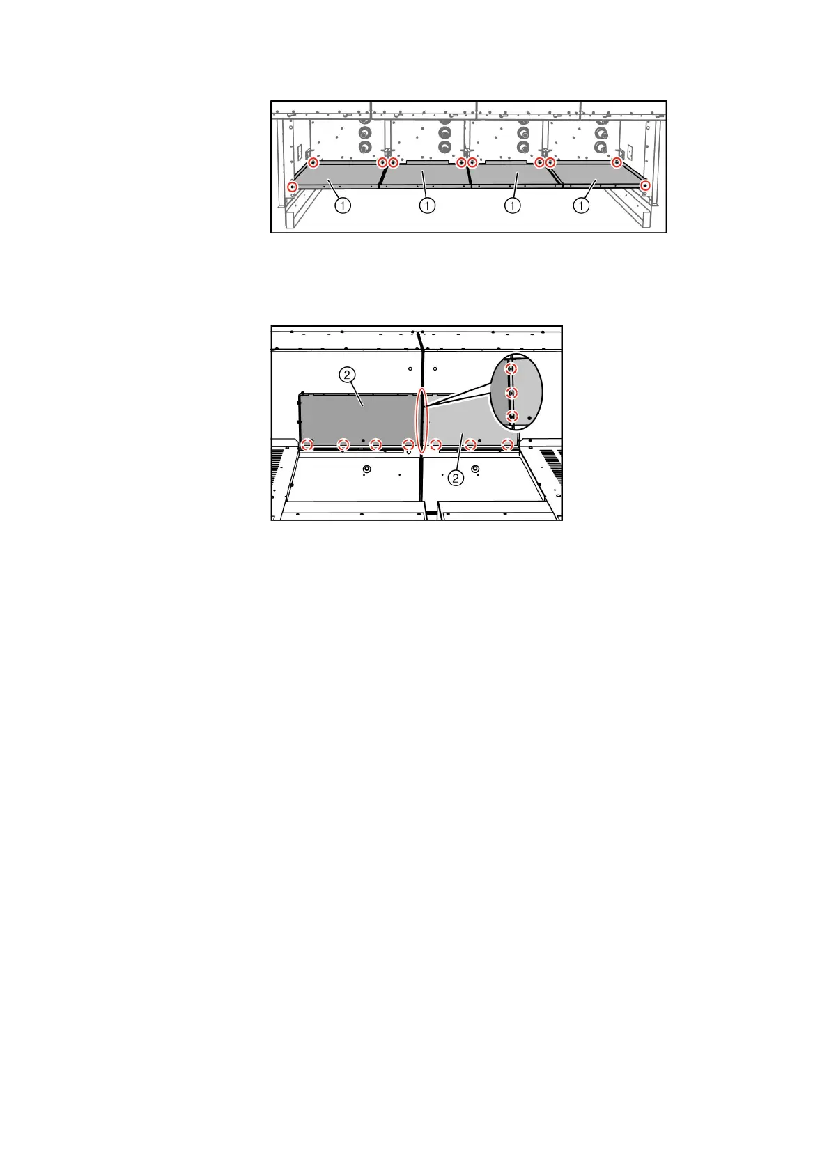
➭ Panel without pressure relief: Bolt supporting angles ① together with the rear walls.
Fig. 104: Mounting the supporting angles (view from above, example)
➭ Panel with 1160 mm high low-voltage compartment: Bolt the connection plate ②
together with the rear wall of the low-voltage compartment. Bolt the connection plate ②
together with the connection plate of the adjacent panel.
Fig. 105: Mounting the connection plate (view from the rear, example)
➭ Bolt the left-hand ④ or right-hand side wall ⑤ together with the cover ③ .
➭ Panel with degree of protection IP3XD, IP31D, IP32D or IP34D: Fasten the termination
angle ⑪ .
➭ Bolt the cover ② together with the panel.
➭ Mount the left-hand ⑥ or right-hand angle plate ⑦ .
➭ Mount the reinforcing plate ⑧ onto the covers mounted before.
➭ Mount the left-hand ⑨ or right-hand sealing angle ⑩ under the following preconditions:
- The panel has a width of 900 mm and is in free-standing arrrangement.
- The adjacent panel has a width of 600 mm.
➭ Repeat the installation of the busbar cover for all panels.
✔ The installation of the busbar cover is completed.