Description
16/293 Revision 11 • INSTALLATION AND OPERATING INSTRUCTIONS • NXPLUS C • 802-9081.9
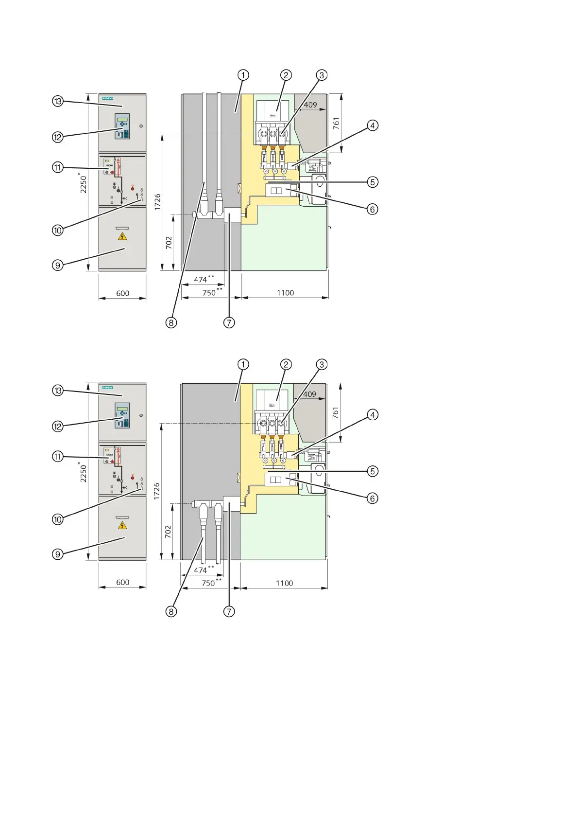
Fig. 8: Circuit-breaker panel with top-rear cable connection (1250 A)
①
Rear pressure relief duct / cable
compartment
②
Busbar voltage transformer (option)
③
Busbar system
④
Three-position disconnector
⑤
Switchgear vessel, hermetically welded,
filled with SF
6
gas, with bursting disc
⑥
Circuit-breaker with vacuum interrupters
⑦
Ring-core current transformer (option)
⑧
Cable with cable plug for outside-cone
plug-in system
⑨
Cover to cable compartment
⑩
Capacitive voltage detecting system
(busbar: left side, cable feeder: right side)
⑪
Control board
⑫
SIPROTEC bay controller (option)
⑬
Low-voltage compartment
* 2650 mm for high low-voltage
compartment
** When only one cable is connected, the
dimension is reduced by 275 mm
Fig. 9: Circuit-breaker panel with bottom-rear cable connection (1250 A)