Description
18/293 Revision 11 • INSTALLATION AND OPERATING INSTRUCTIONS • NXPLUS C • 802-9081.9
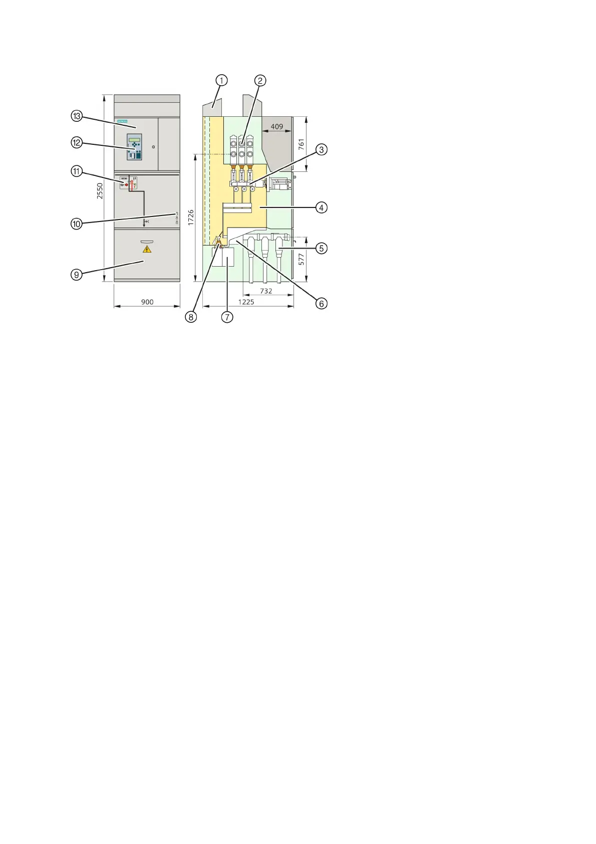
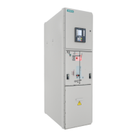
Fig. 12: Disconnector panel (2000 A and 2500 A)
①
Air guide
②
Busbar system
③
Three-position disconnector
④
Switchgear vessel, hermetically welded, filled with SF
6
gas, with bursting disc
⑤
Cable with cable plug for outside-cone plug-in system
⑥
Ring-core current transformer (option)
⑦
Voltage transformer (option)
⑧
Voltage transformer disconnector (option)
⑨
Cover to cable compartment
⑩
Capacitive voltage detecting system (busbar: left side,
cable feeder: right side)
⑪
Control board
⑫
SIPROTEC bay controller (option)
⑬
Low-voltage compartment


 To Next Page