Description
20/293 Revision 11 • INSTALLATION AND OPERATING INSTRUCTIONS • NXPLUS C • 802-9081.9
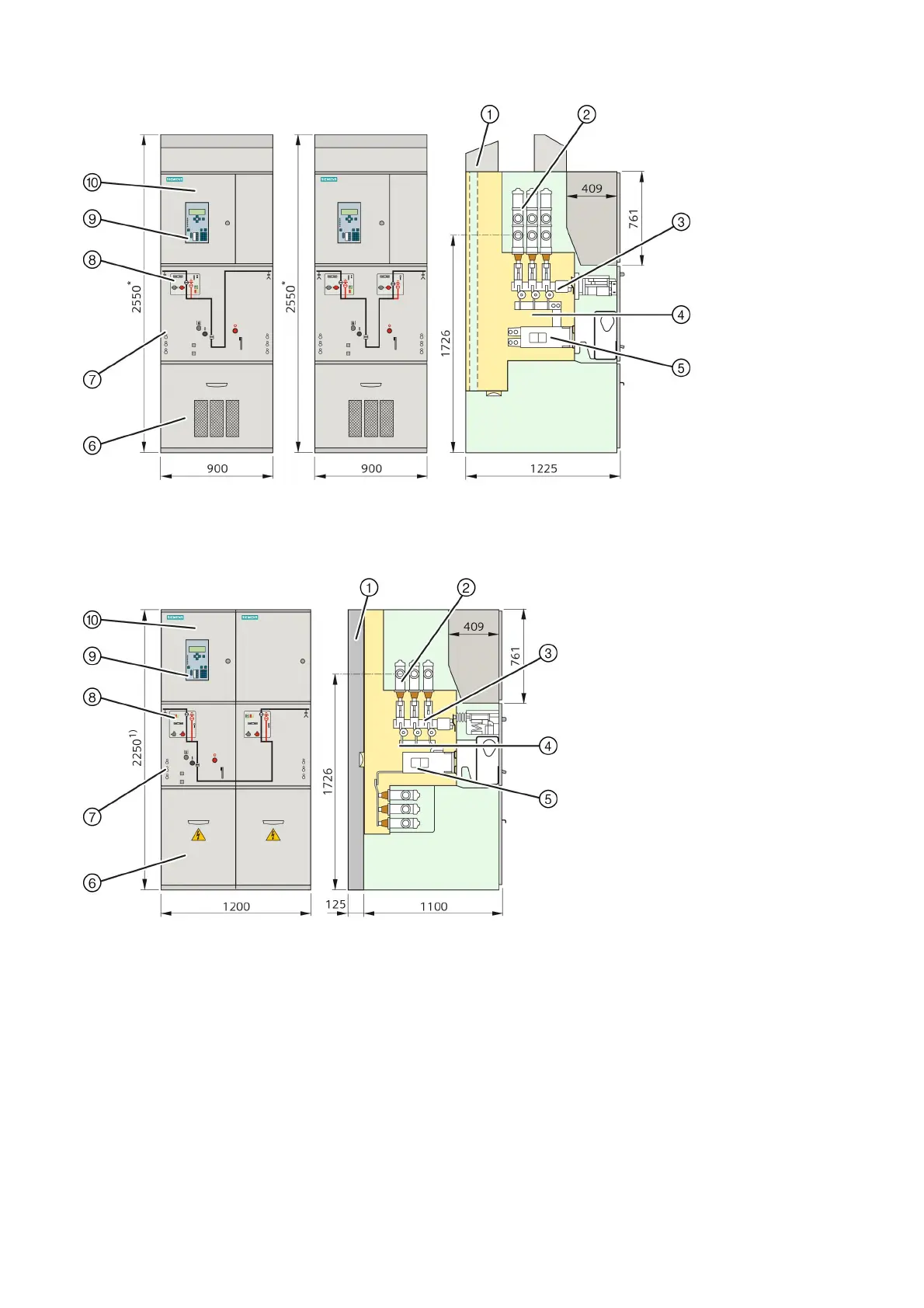
Fig. 15: Bus sectionalizer panel with one or two disconnectors (1 panel spacing) (2000 A and
2500 A)
①
Air guide
②
Twin busbar system
③
Three-position disconnector
④
Switching-device vessel,
hermetically welded, filled
with SF
6
gas, with bursting
disc
⑤
Circuit-breaker with
vacuum interrupters
⑥
Cable compartment cover
(only for 2500 A with
ventilation)
⑦
Socket for capacitive
voltage detecting system
(busbar: left side, cable
feeder: right side)
⑧
Control board
⑨
SIPROTEC bay controller
(option)
⑩
Low-voltage compartment
* 2650 mm for high low-
voltage compartment
Fig. 16: Bus sectionalizer panel with disconnector (2 panel spacings) (1250 A)
①
Rear pressure relief duct (option)
②
Busbar system
③
Three-position disconnector
④
Switching-device vessel, hermetically
welded, filled with SF
6
gas, with
bursting disc
⑤
Circuit-breaker with vacuum interrupters
⑥
Cable compartment cover
⑦
Socket for capacitive voltage detecting
system (busbar: left side, cable feeder:
right side)
⑧
Control board
⑨
SIPROTEC bay controller (option)
⑩
Low-voltage compartment
1) 2650 mm for high low-voltage
compartment