802-9081.9 • INSTALLATION AND OPERATING INSTRUCTIONS • NXPLUS C • Revision 11 85/293
Installation
Stipulations for evenness
and straightness
Evenness/straightness tolerance according to DIN 43661: 1 mm for 1 m length, 2 mm over
the width of the complete switchgear.
• Determine level differences between the installation surfaces of the panels using a
measuring sheet, and compensate with shims (0.5 - 1.0 mm).
Fig. 46: Measuring sheet for the foundation (example)
Floor openings and fixing points
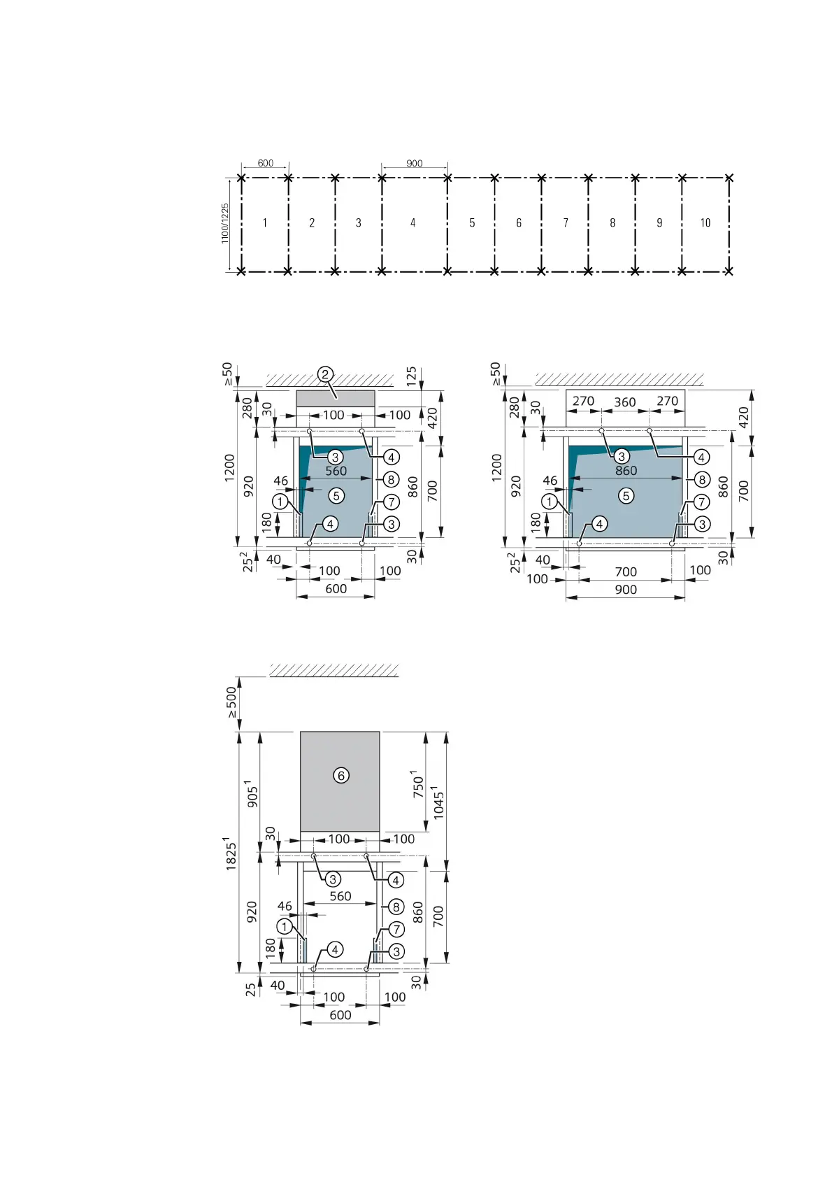
Fig. 47: Panel with 600 mm panel width
Fig. 48: Panel with 900 mm panel width
Fig. 49: Circuit-breaker panel with top-rear
cable connection
①
Left-side floor opening for control cables
②
Pressure relief duct (option)
③
Fixing point
④
Fixing point (additionally for resistance against
shock, vibration, earthquakes)
⑤
Floor opening for high-voltage cables
⑥
Cable compartment / pressure relief duct
⑦
Right-hand floor opening for control cables (only
required for zero-sequence current transformers in
the cable basement)
⑧
Cross member
1
When only one cable is connected, the dimension is
reduced by 275 mm
2
45 mm for deep cable compartment cover