EasyManua.ls Logo

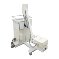
Siemens POLYMOBIL Plus - Service Manual

Siemens POLYMOBIL Plus
50 pages
To Next Page IconTo Next Page
Loading...
POLYMOBIL Plus
English
Print No.: SPR8-125.061.02.01.02 Release Date: 01.00
Replaces: n.a.
© Siemens AG 2000
The reproduction, transmission or
use of this document or its contents
is not permitted without express
written authority. Offenders will be
liable for damages. All rights,
including rights created by patent
grant or registration of a utility
model _or_ design,_are_ reserved.
SP
Service Instructions
From Serial-No. 10100

Table of Contents

Other manuals for Siemens POLYMOBIL Plus

Questions and Answers:

Siemens POLYMOBIL Plus Specifications

General IconGeneral
TypeMobile X-ray System
X-ray Tube Focal Spot0.6 / 1.2 mm
kV Range40 - 125 kV
mAs Range320 mAs
DisplayHigh-resolution Touchscreen
Image Receptor CompatibilityCR cassettes

Summary

Prerequisites

Text Emphasis and Warnings

Defines WARNING, CAUTION, and NOTICE terms for safety and operational guidance.

Required Documents

Lists essential documents like block diagrams and function descriptions for service.

Tools and Equipment Required

Lists necessary tools, meters, and auxiliary devices for service procedures.

Safety Information and Protective Measures

Provides critical safety guidelines and protective measures to be followed during service.

Replacing Damaged or Missing Screws

Specifies requirements for replacing screws, including material and tensile strength.

Cleaning Procedures

Outlines safe methods and agents for cleaning the unit.

Checking the Assemblies

Preparation for Assembly Checks

Instructions on how to prepare the system for inspection of its components.

Component Identification: LEDs, Fuses, Test Points, Potentiometers

Details the location and function of various electronic components on the D915 board.

D925: Rotating Anode Starter, Filament Inverter, ON;OFF Circuit

Explains how to check the D925 assembly, including LEDs, fuses, and voltage points.

Power Supply Units: U1 and U2

Procedures for checking the U1 (5V/15V) and U2 (12.5V) power supply units.

D950 Capacitor Charging Circuit

Steps for checking the D950 circuit, including LEDs, fuses, and test points.

D970 Capacitor Bank

Details on checking the D970 capacitor bank, including LEDs and fuses.

LED Status Indicators

Describes the expected LED states for different operating modes (OFF, standby).

Troubleshooting

Error Messages Overview

Lists and categorizes error codes encountered during operation.

Troubleshooting Specific Error Codes

Provides detailed steps to diagnose and resolve specific error messages.

Service Programs

Overview of Available Service Programs

Lists and briefly describes the functions of various service programs (Pr. 1-9).

Measurements

Line Voltage Check

Verifies the input line voltage and its automatic adjustment feature.

KVact and Itube Measurement

Instructions for measuring actual kV and tube current using an oscilloscope.

Capacitor Charging Circuit Analysis

Details on measuring the charging frequency of the capacitor bank.

Capacitor Charging Current Measurement

Procedure to measure the current during capacitor charging.

Capacitor Voltage and Charging Time

How to measure capacitor voltage (Uc) and the time taken for charging.

Rotating Anode Starter: Acceleration

Measuring stator currents during the acceleration phase of the anode starter.

Rotating Anode Starter: Brakes

Measuring stator currents during the braking phase of the anode starter.

KV Control: Max. Inverter Frequency

Checking and setting the maximum main inverter frequency.

Oscillating Current Measurement

Procedure for measuring the oscillating current using a current transformer.

kVact and kVnom Measurement

Measuring and comparing actual kV (kVact) with nominal kV (kVnom).

Error in kVact Acquisition Diagnosis

Troubleshooting steps for errors related to kVact signal acquisition.

Filament Circuit Testing

Procedures for testing the filament circuit, including frequency and current.

Setting Max. Filament Inverter Frequency

Adjusting the maximum filament inverter frequency using potentiometer P3.

Filament Nominal Value Measurement

Measuring the filament nominal value, which is factory-set.

Setting Tube Current for Exposure

Procedure to reset and set the tube current for each exposure.

Testing and Setting mAs Counter

Verifies and adjusts the mAs counter against the set value.

Coincidence of Light and Radiation Fields Procedure

Steps to perform and test the alignment of light and radiation fields.

Coincidence Evaluation and Tolerance

Methods for measuring deviations and checking tolerance for field coincidence.

Testing and Readjusting the Counterbalance

Procedures for testing and readjusting the C-arm counterbalance mechanism.

Replacing Important Components

Replacing the Single Tank Generator

Detailed steps for removing and replacing the single tank generator.

Replacing the Collimator

Instructions for completely replacing the collimator unit.

Replacing the Localizer Lamp

Procedure for replacing the light localizer lamp.

Replacing the Steering Caster

Steps for removing and installing a new steering caster.

Replacing the Capacitor Bank

Instructions for safely replacing the capacitor bank.

Related product manuals