H
hawkinstoddAug 27, 2025
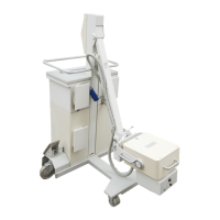
How to troubleshoot + 15 V - Error in Siemens POLYMOBIL Plus?
- Eedwin60Aug 27, 2025
To troubleshoot a '+ 15 V - Error' in Siemens Medical Equipment, check the fuse on power supply U1 and determine if power supply U1 is defective.