Digital modules
8.6 SM 326; DO 10 x DC 24V/2A (6ES7326-2BF01-0AB0)
Fail-safe signal modules
Installation and Operating Manual, 01/2010, A5E00085586-10
151
8.6.5 Parallel Connection of Two Outputs for Dark Period Suppression
Applications
All applications (3, 4, 5 and 6) support parallel operation of two outputs for dark period
suppression in safety mode.
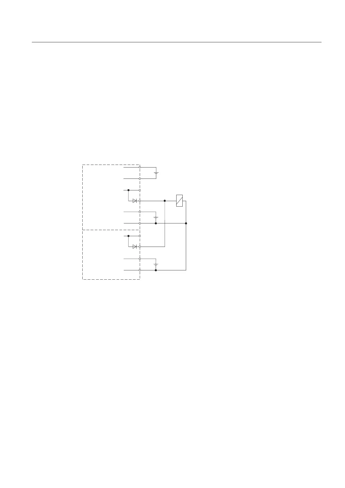
Wiring scheme
Interconnect two
opposite outputs
by means of a series diode in order to form a single
output. The parallel circuit in combination with an internal test coordination between the
outputs 0 to 4 and 5 to 9 suppresses the "0" test pulse (dark period).
/
0
'2
/
0
/
0
60
'2['&9$
ULJKW
FKDQQHOVWR
OHIW
FKDQQHOVWR
Figure 8-48 Wiring two outputs in parallel for dark period suppression of the SM 326; DO 10 x DC
24V/2A
You assign the fail-safe signal module parameters as described for the various applications
on the previous pages. The interconnection does not require any additional parameters.
Always set the interconnected outputs in parallel instead of setting only one output. Process
signals of a redundant I/O system require four outputs with series diode.

 Loading...


