Table 4-7 Operate Level
Parameter Attribute Value
I> Operate level 110 % of I> ±5 %
Table 4-8 Operate Time
Parameter Attribute Value
Operate time char = IEC-NI ±5 % absolute or ±40 ms
Time multiplier setting (k) 0.09 –
NOTE
The IDMT function is not applicable for the ground fault I
N
.
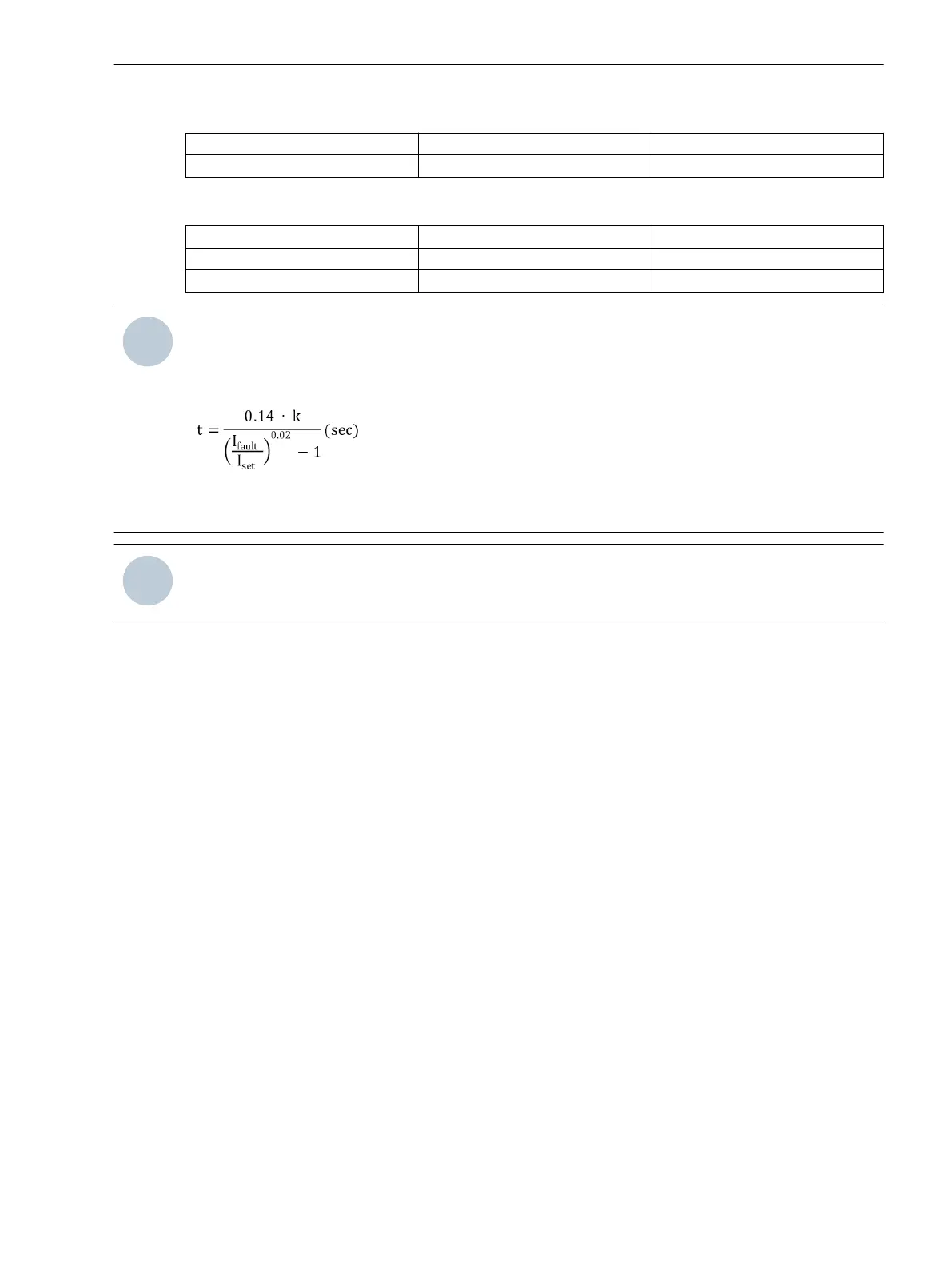
If tI> is set to zero, the NI trip time curve according to the IEC characteristics is calculated based on the
following formula.
I
fault
is the fault current. I
set
is the setting value of the pickup current.
The fixed value of k is 0.09.
NOTE
For setting the IDMT characteristics curves, set tI> = 0.
Ground-Fault Parameter Active Group Setting
The device provides 2 groups of settings (Group 1 and Group 2) for the Neutral-point treatment param-
eter (solid, resonant, isolated) and Ground-fault parameters (I
N
>, tI
N
>, V
NG
>, tV
NG
>, and I
dir
).
You can select the active group and its group parameter from HMI and Modbus, by holding register (address
42) or by turning ON the coil 12. When the device is indicating a fault, you cannot change the active group
and its parameters.
At any time, only one selected group of settings is active. These parameters are used for detecting the ground
fault.
For more information about the active-group switching coil, refer to Table B-10.
For more information about the active group, refer to Active Group, Page 121.
Fault Indication
When the device detects a fault, the following components are activated:
•
LED
The red LED is turned on and indicates a fault.
•
LCD
The LCD displays fault current values with the fault type.
•
Modbus
The device sends the fault current, fault type, and additional fault information to the RTU.
If a fault is detected, the red LED flashes every 1 s if the device is not powered through an auxiliary supply.
4.1.6
4.1.7
Device Functions
4.1 Description
SICAM, Feeder Condition Monitor, Manual 37
E50417-H8940-C580-A4, Edition 03.2019