Pickup Measuring Element
1 2 3 N
1, 2 I
1
V
2
- V
3
I
2
V
3
- V
1
– – – –
2, 3 – – I
2
V
3
- V
1
I
3
V
1
- V
2
– –
1, 3 I
1
V
2
- V
3
– – I
3
V
1
- V
2
– –
1, 2, N I
1
V
2
- V
3
I
2
V
3
- V
1
– – I
N
V
NG
6
2, 3, N – – I
2
V
3
- V
1
I
3
V
1
- V
2
I
N
V
NG
6
1, 3, N I
1
V
2
- V
3
– – I
3
V
1
- V
2
I
N
V
NG
6
1, 2, 3 I
1
V
2
- V
3
I
2
V
3
- V
1
I
3
V
1
- V
2
– –
1, 2, 3, N I
1
V
2
- V
3
I
2
V
3
- V
1
I
3
V
1
- V
2
I
N
V
NG
6
Direction Determination of Phase Elements
In the device, the directional overcurrent element operates for any faults either in forward direction or in
reverse direction.
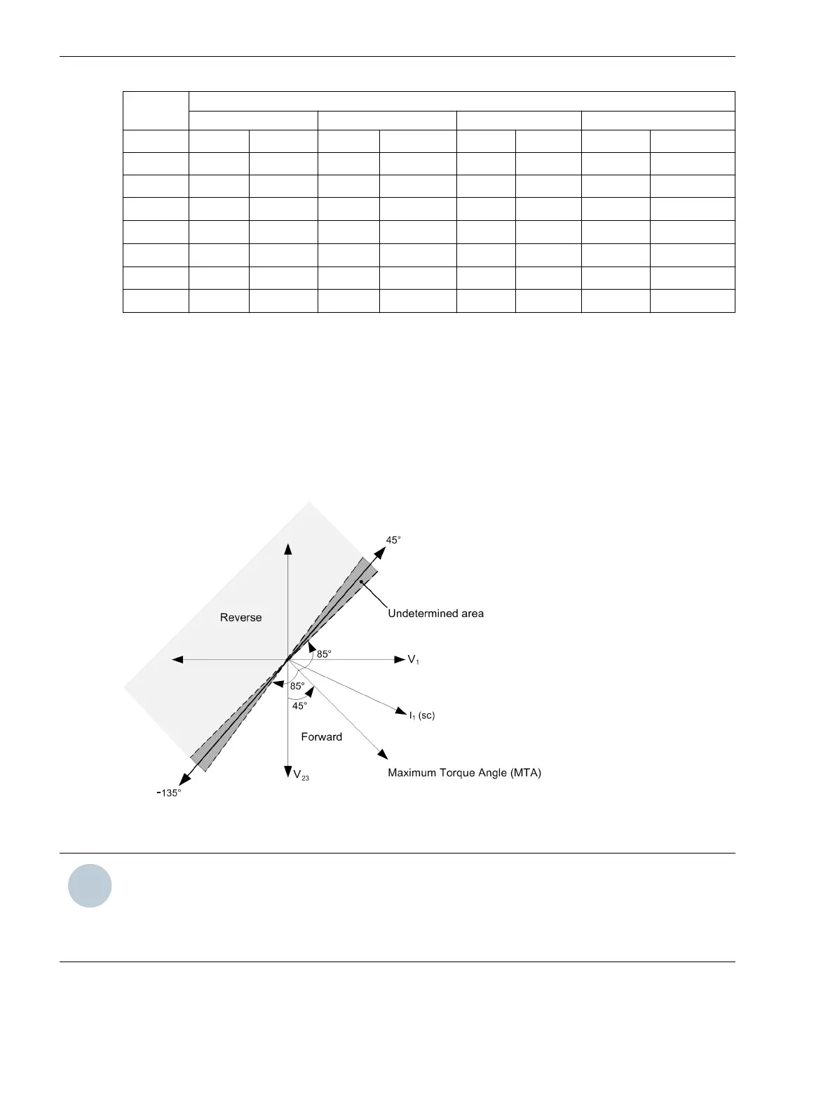
The directional determination of phase elements works in the quadrature connection to prevent the loss of
polarizing quantity for close-in phase faults. Each current element has a direction by a voltage derived from
the other 2 phases. This connection introduces a 90° phase jump (current leading voltage) between reference
voltages and operating quantities (currents). A fault is determined to be in the selected direction if its phase
relationship lies within a quadrant of ± 85° on either side of the characteristic angle. It is hard-coded as +45°.
[dw_sfcm-dirdetphaelm, 1, en_US]
Figure 4-10 Direction Determination of Phase Elements
NOTE
The undetermined area for the device MLFB 6MD2321-1AA00-1AA0 is 10° and the respective angles
change accordingly.
The undetermined area for the device MLFB 6MD2322-1AA00-1AA0 is 20° and the respective angles
change accordingly.
4.1.16
Device Functions
4.1 Description
42 SICAM, Feeder Condition Monitor, Manual
E50417-H8940-C580-A4, Edition 03.2019