NOTE
The undetermined area for the device MLFB 6MD2321-1AA00-1AA0 is 10° and the respective angles
change accordingly.
The undetermined area for the device MLFB 6MD2322-1AA00-1AA0 is 20° and the respective angles
change accordingly.
For more information about ground-fault direction of solidly grounded system, see Table A-3 and refer to the
Fault Parameter > Ground-Fault Detection > Neutral-point Treatment menu.
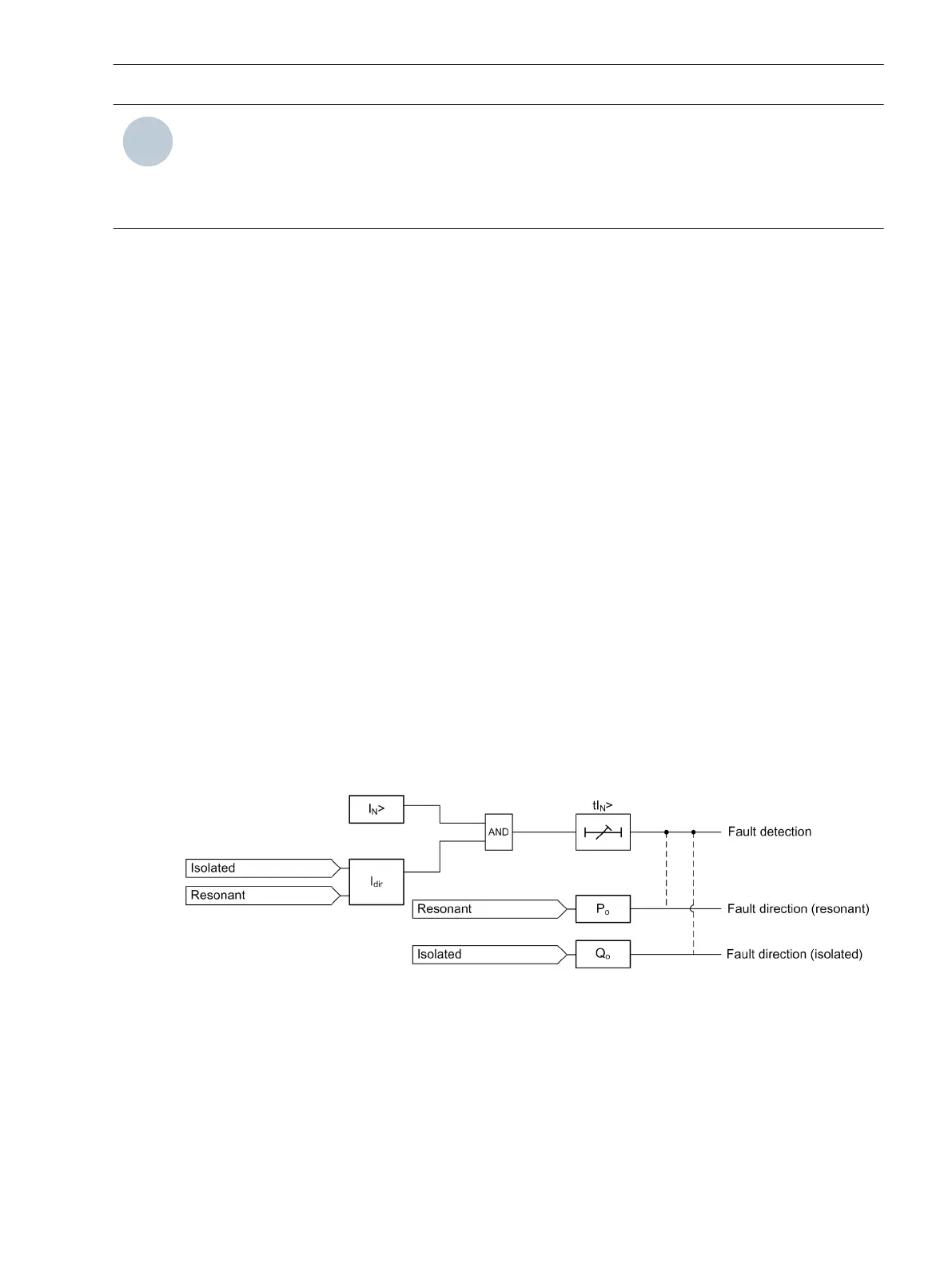
Ground-Fault Detection with Cos φ/Sin φ Measurement
The ground-fault detection with cos φ/sin φ measurement method is used to detect the ground fault based on
the active part of the current (resonant system) or reactive part of the current (isolated system). The ground-
fault detection with cos φ/sin φ measurement method is enabled when the I
dir
(user-settable parameter for
the resistive part of the ground current) parameter is configured to the values as in Table 4-9. If I
dir
is set to 0,
the device detects the ground fault based on the vector method.
The ground-fault detection with cos φ/sin φ measurement method is only applicable for resonant-grounded
systems and isolated-grounded systems.
If the ground current ((I
N
>) and the resistive current exceed the set threshold (I
N
> and I
dir
respectively) and if
the time delay tI
N
> is greater than the set threshold, the device indicates a fault.
If I
dir
is set to 0 (vector method), irrespective of the selected ground-type connection, the total ground current
is compared with the set current I
N
> for fault detection.
For resonant-ground connections, if I
dir
is not 0 (ground-fault detection with cos φ/sin φ measurement
method), the active part of the ground current is compared with I
dir
in addition to the total ground current and
I
N
> for ground-fault detection.
For isolated-ground connections, if I
dir
is not 0 (ground-fault detection with cos φ/sin φ measurement
method), the reactive part of the ground current is compared with I
dir
in addition to the total ground current
and I
N
> for ground-fault detection.
For more information about I
dir
parameters, see Table A-3 and refer to the Fault Parameters > Ground-Fault
Detection menu.
The following logic diagram illustrates the ground-fault detection with cos φ/sin φ measurement method.
[lo_sfcm-grndfltdet-cossine, 2, en_US]
Figure 4-14 Logic Diagram for Ground-Fault Detection with Cos φ/Sin φ Measurement Method
The following table displays the I
dir
range and the ground-fault detection with cos φ/sin φ measurement
method status:
4.1.20
Device Functions
4.1 Description
SICAM, Feeder Condition Monitor, Manual 45
E50417-H8940-C580-A4, Edition 03.2019