Sensor Connections
The following table shows how the current and voltage sensors are designated as per the terminals.
[dw_sfcmtrml, 2, en_US]
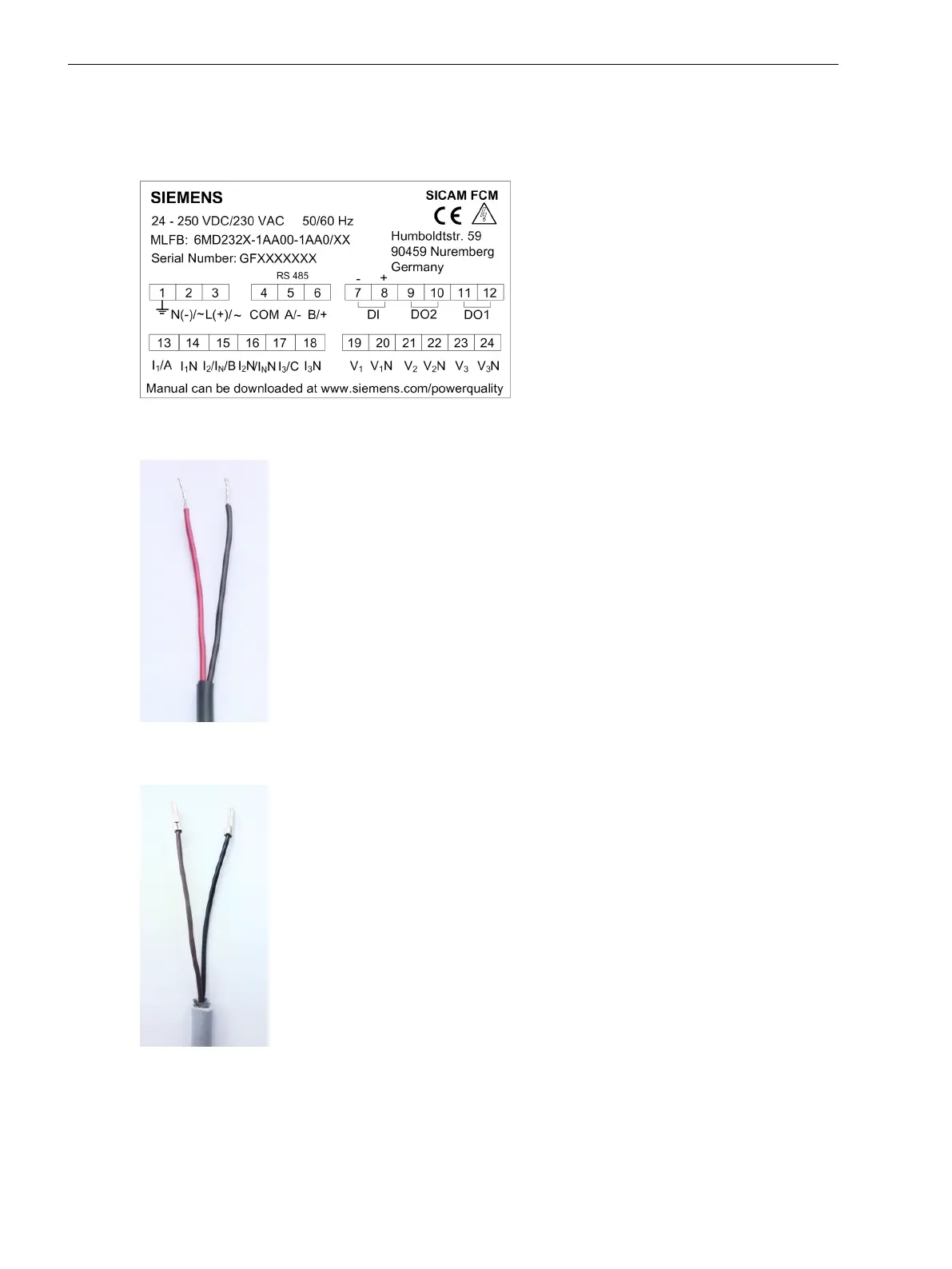
Figure 7-7 Terminal Diagram
[ph_current_sensor_wires, 1, --_--]
Figure 7-8 Phase-Current Sensors Cable Leads (Red/Black)
[ph_voltage_sensor_wires, 1, --_--]
Figure 7-9 Phase-Voltage Sensors Cable Leads (Black/Brown)
7.3
Connection Diagrams
7.3 Sensor Connections
74 SICAM, Feeder Condition Monitor, Manual
E50417-H8940-C580-A4, Edition 03.2019