Hardware Components
In this manual, SICAM FCM is also referred as device.
•
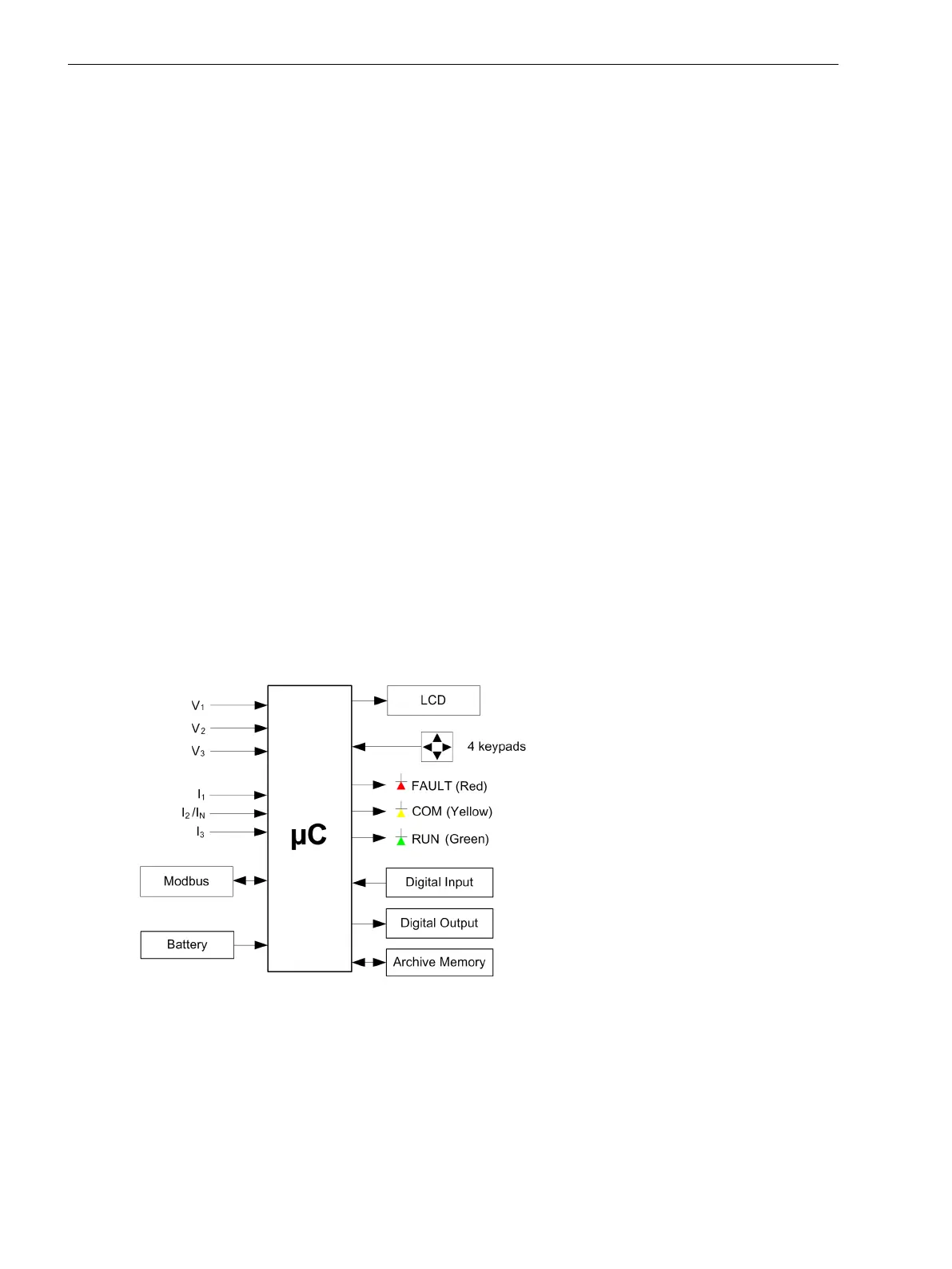
Microcontroller
The device uses a low-power ARM MCU which includes high-precision 16-bit ADCs.
•
Battery
The device contains a battery with 3.6 V and a capacity of 1.2 Ah.
•
LCD
LCD is used to view real-time values, events, archives, and device parameters.
•
Keypads
The 4 navigation keys are used to navigate through the device menu and to select the desired parame-
ters. The functions of the navigation keys are specific to different menu sections.
•
LEDs
The device consists of 3 LEDs which indicate the status of the process.
– FAULT (Red)
Indicates when any distribution-system fault is detected
– COM (Yellow)
Indicates that the communication is active between Modbus master and the SICAM FCM
– RUN (Green)
Indicates the healthy condition of the device and operating on the auxiliary voltage
•
Digital Input
The device consists of 1 digital input for resetting the fault indication.
•
Digital Output
The device consists of 2 digital outputs for indicating fault conditions.
[dw_sfcmhwbd, 1, en_US]
Figure 3-1 SICAM FCM Hardware Block Diagram
3.1
Hardware Components and Drawings
3.1 Hardware Components
22 SICAM, Feeder Condition Monitor, Manual
E50417-H8940-C580-A4, Edition 03.2019