Connection Diagrams
This chapter describes the various possibilities to connect the device to the medium-voltage system.
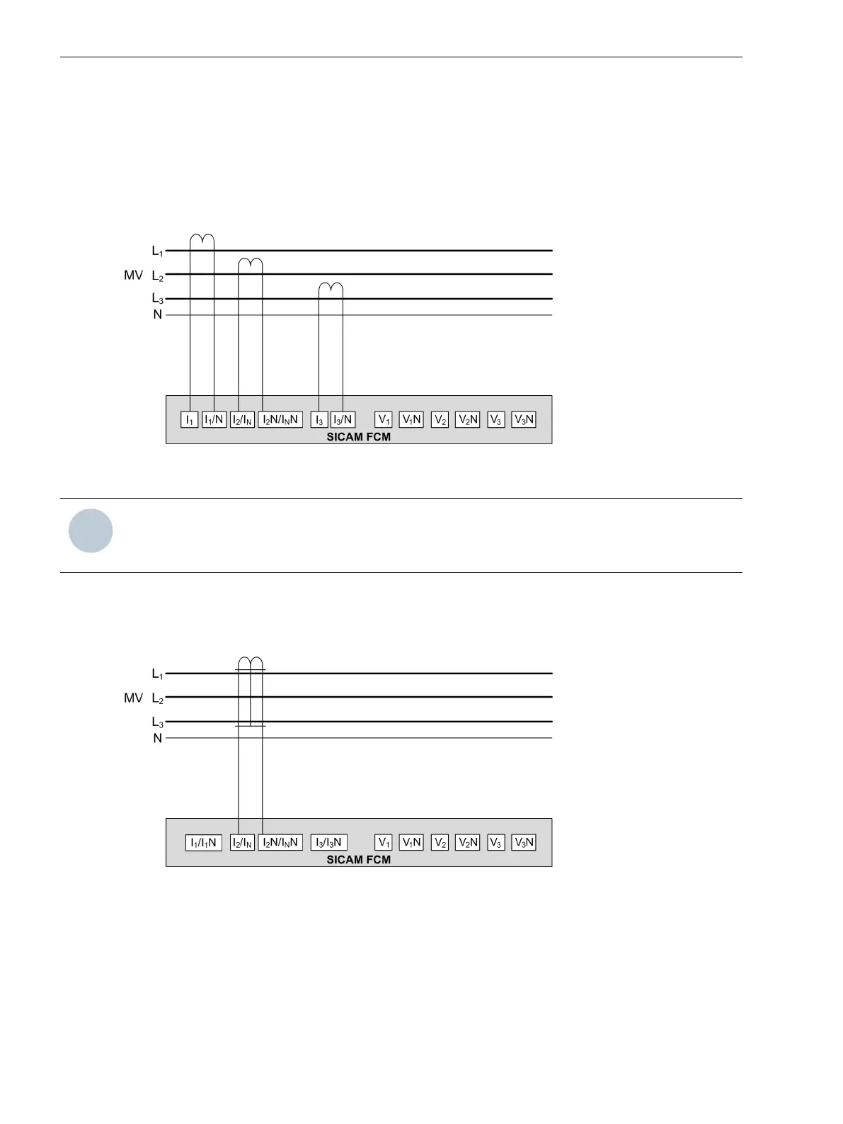
Fault Passage Indicator
The device can be used as a dedicated Fault Passage Indicator (FPI) by using only the 3 current inputs. No
directional fault information is provided in this scheme.
[dw_sfcm-sfpi, 2, en_US]
Figure 7-1 SICAM FCM as Fault Passage Indicator
NOTE
In this connection scheme, the accuracy of ground-current measurements cannot be guaranteed for
isolated/resonant ground connection.
Ground-Fault Indicator
The device can be used as a dedicated ground-fault indicator by using the ground-current sensor. The
following scheme shows how the device works as a non-directional ground-fault indicator (50 G).
[dw_sfcm_grdfltindi, 2, en_US]
Figure 7-2 SICAM FCM as Ground-Fault Indicator
Fault Detector
The device can be used as a fault detector by providing fault information with directional information. This
requires an additional low-power voltage transformer of 3.25/√3 V or 100/√3 V sensors in the medium-voltage
system or a direct connection to 230 V or when it is connected in the VDS.
For more information about VDS, see chapter 4.1.32 Voltage Measurement via Integrated Voltage-Detecting
Systems.
7.1
Connection Diagrams
7.1 Connection Diagrams
70 SICAM, Feeder Condition Monitor, Manual
E50417-H8940-C580-A4, Edition 03.2019