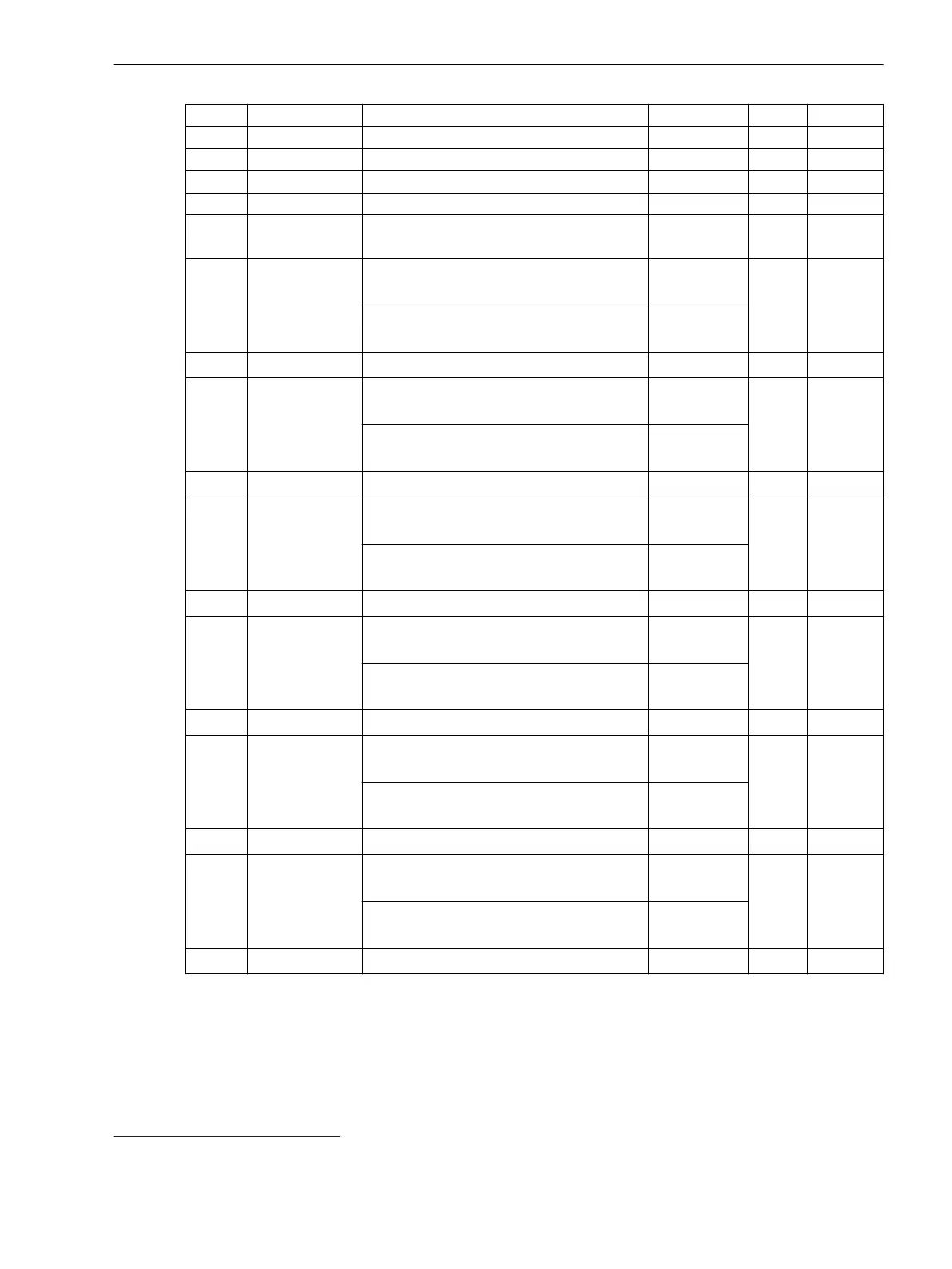
Address Min/Max Value Parameters Default Unit Type
75 0 to 100 Number of pulses for operate 0 – uInt16
76 0 to 100 Number of pulses for monitoring 0 – uInt16
77 0, 2 to 999 Nos det. 0 – ulnt16
78 0 to 600 T-det. ext 0 s ulnt16
79
11
0
1
Correction factor disabled
Correction factor enabled
0 – ulnt16
80 0, 700 to 3000 V
1
magnitude factor
(correction factor disabled)
0 1/1000 ulnt16
V
1
magnitude factor
(correction factor enabled)
1000
81 -500 to 500 V
1
angle offset 0 min Int16
82 0, 700 to 3000 V
2
magnitude factor
(correction factor disabled)
0 1/1000 ulnt16
V
2
magnitude factor
(correction factor enabled)
1000
83 -500 to 500 V
2
angle offset 0 min Int16
84 0, 700 to 3000 V
3
magnitude factor
(correction factor disabled)
0 1/1000 ulnt16
V
3
magnitude factor
(correction factor enabled)
1000
85 -500 to 500 V
3
angle offset 0 min Int16
86 0, 800 to 1200 I
1
magnitude factor
(correction factor disabled)
0 1/1000 ulnt16
I
1
magnitude factor
(correction factor enabled)
1000
87 -500 to 500 I
1
angle offset 0 min Int16
88 0, 800 to 1200 I
2
/I
N
magnitude factor
(correction factor disabled)
0 1/1000 ulnt16
I
2
/I
N
magnitude factor
(correction factor enabled)
1000
89 -500 to 500 I
2
/I
N
angle offset 0 min Int16
90 0, 800 to 1200 I
3
magnitude factor
(correction factor disabled)
0 1/1000 ulnt16
I
3
magnitude factor
(correction factor enabled)
1000
91 -500 to 500 I
3
angle offset 0 min Int16
For more information about register-type data – input registers, see B.5 Register-Type Data – Input Registers.
11
Default values in holding addresses 80 to 91 are dependent on whether the parameter Correction factor (holding register 79) is disa-
bled or enabled.
Modbus Registers
B.2 Implementation of the Modbus Protocol
SICAM, Feeder Condition Monitor, Manual 99
E50417-H8940-C580-A4, Edition 03.2019