Terminal Diagram
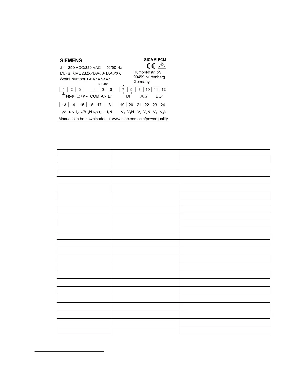
The terminal diagram is located on top of the housing and displays the terminal numbers and terminals.
[dw_sfcmtrml, 2, en_US]
Figure 3-2 Terminal Diagram
Table 3-1 Terminal Specifications
Terminal Number Terminal Name Description
(1) 1 Functional ground
(2) N(-)/~ Auxiliary voltage
(3) L(+)/~ Auxiliary voltage
(4) COM Modbus - Common
(5) A/- Modbus - T
x
(6) B/+ Modbus - R
x
(7) DI1(-) Digital input (-)
(8) DI1(+) Digital input (+)
(9) DO2 Digital output 2
(10) DO2 Digital output 2
(11) DO1 Digital output 1
(12) DO1 Digital output 1
(13) I
1
/A Phase current I
1
(14) I
1
N Neutral
(15) I
2
/I
N
/B Phase current I
2
or ground current I
N
(16) I
2
/I
N
N Neutral
(17) I
3
/C Phase current I
3
(18) I
3
N Neutral
(19) V
1
Voltage input V
1
(20)
V
1
N
5
Neutral
(21) V
2
Voltage input V
2
(22)
V
2
N
5
Neutral
(23) V
3
Voltage input V
3
(24)
V
3
N
5
Neutral
3.2
5
V
1
N, V
2
N, V
3
N are internally shorted
Hardware Components and Drawings
3.2 Terminal Diagram
SICAM, Feeder Condition Monitor, Manual 23
E50417-H8940-C580-A4, Edition 03.2019