3 Low-Power Voltage Sensor, 3 Low-Power Current Sensor
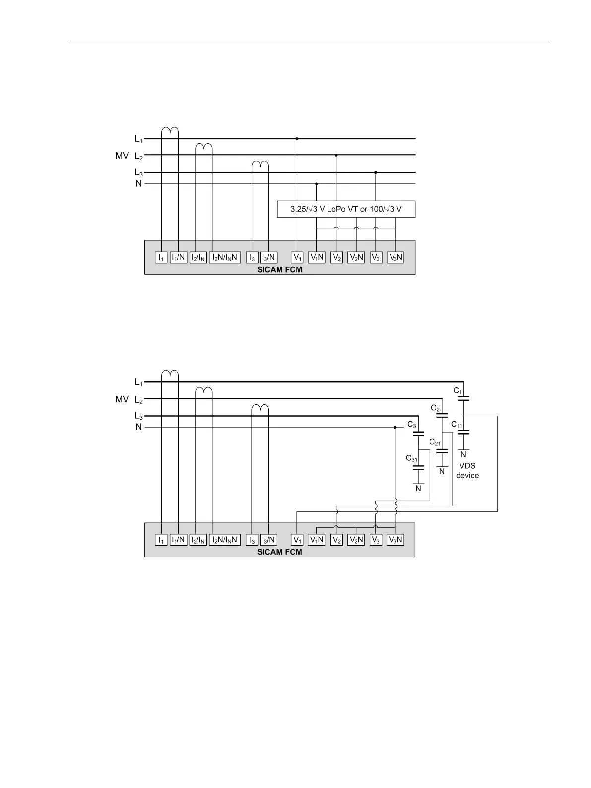
In a medium-voltage system, the device is connected to the voltage inputs V
1
, V
2
, and V
3
via low-power
voltage transformers of 3.25/√3 V or 100/√3 V. The 3 low-power current sensors are connected to the current
inputs I
1
, I
2
, and I
3
. This scheme is used for a solidly grounded system and the I
N
value is calculated.
[dw_sfcm-fltdtct-lopovt, 2, en_US]
Figure 7-3 SICAM FCM as Fault Detector – 3 Low-Power Voltage Sensors and Current Sensors with 3
Phase Currents for MLFB 6MD2321-1AA00-1AA0
In a medium-voltage system, the device is connected to the voltage inputs V
1
, V
2
, and V
3
via the 4 V to 30 V
VDS system. The 3 low-power current sensors are connected to the current inputs I
1
, I
2
, and I
3
. These connec-
tion diagrams are used for a solidly grounded system and the I
N
value is calculated.
[dw_sfcm-fltdtct-nonvt, 2, en_US]
Figure 7-4 SICAM FCM as Fault Detector – 3 Low-Power Voltage Transformer and Current Transformer
with 3 Phase Currents for MLFB 6MD2322-1AA00-1AA0
3 Low-Power Voltage Sensor, 2 Phase Current, and Sensitive Ground-Current Sensor
In a medium-voltage system, the device is connected to the voltage inputs V
1
, V
2
, and V
3
via low-power
voltage sensors of 3.25/√3 V or 100/√3 V. The 3 low-power current sensors are connected to I
1
, I
2
/I
N
, I
3
with I
N
connected to the sensitive ground-current sensors. This scheme is used for isolated/resonant-grounded
systems and the I
2
value is calculated.
Connection Diagrams
7.1 Connection Diagrams
SICAM, Feeder Condition Monitor, Manual 71
E50417-H8940-C580-A4, Edition 03.2019