[dw_sfcm-fltdtct-ressnt, 2, en_US]
Figure 7-5 SICAM FCM as Fault Detector – 3 Low-Power Voltage Sensor with 2 Phase Currents and Sensi-
tive Ground-Current Sensor for MLFB 6MD2321-1AA00-1AA0
In a medium-voltage system, the device is connected to the voltage inputs V
1
, V
2
, and V
3
via 4 V to 30 V VDS
system. The 3 low-power current sensors are connected to I
1
, I
2
/I
N
, I
3
with I
N
connected to the sensitive
ground-current sensors. These connection diagrams are used for isolated/resonant-grounded systems and the
I
2
value is calculated.
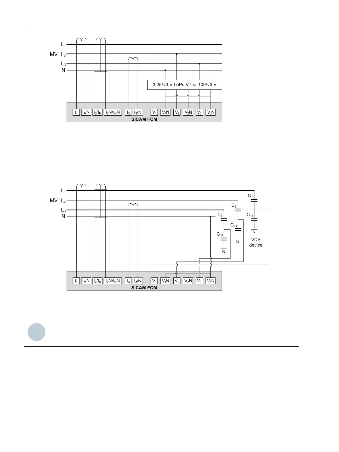
[dw_sfcm-fltdtct-capsnt, 2, en_US]
Figure 7-6 SICAM FCM as Fault Detector – 3 Low-Power Voltage Transformer with 2 Phase Currents and
Sensitive Ground-Current Sensor for MLFB 6MD2322-1AA00-1AA0
NOTE
During electrical installation, all the rules and regulations of power systems must be observed.
Low-Voltage (230 V) Measurement
For more information about low-voltage (230 V) measurement, see chapter 4.1.30 Low-Voltage Measure-
ment.
Medium-Voltage/Low-Voltage Measurement
For more information about medium-voltage/low-voltage measurement, see chapter 4.1.31 Determination of
Medium Voltage via Low-Voltage Measurements.
Connection Diagrams
7.1 Connection Diagrams
72 SICAM, Feeder Condition Monitor, Manual
E50417-H8940-C580-A4, Edition 03.2019